CONTROL PANEL OPERATING PROCEDURES
3-9
8. With the unit firing properly, it will be
controlled by the temperature controller cir-
cuitry. The FIRE RATE will be continuously
displayed on the front panel bargraph.
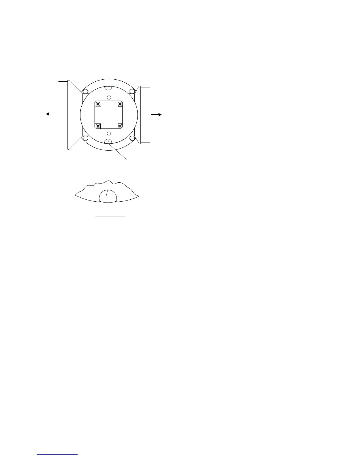
DIAL
(DETAIL "A")
BURNER
BLOWER
DETAIL "A"
2
5
Figure 3-6.
Air/Fuel Valve In Ignition Position
Once the demand for heat has been satisfied,
the Control Box will turn off the gas valve. The
blower relay will be deactivated and the Air/Fuel
Valve will be closed. Standby will be displayed.
3.9. START/STOP LEVELS
The start and stop levels are the fire rate
percentages that start and stop the unit, based
on load. These levels are Factory preset for
natural gas as follows:
• Start Level: 20%
• Stop Level: 16%
Normally, these settings should not require
adjustment.
For Dual-Fuel units operating on propane, the
start and stop levels must be changed to the
following values:
• Start Level: 28%
• Stop Level: 24%
See Appendix K for Dual Fuel switch-over
instructions when operating on propane.
 Loading...