INSTALLATION
2-3
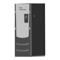
BOILER SUPPLY
(4"-150# FLG'D CONN.)
(4"-150# FLG'D CONN.)
BOILER RETURN
Figure 2.3
Supply and Return Location
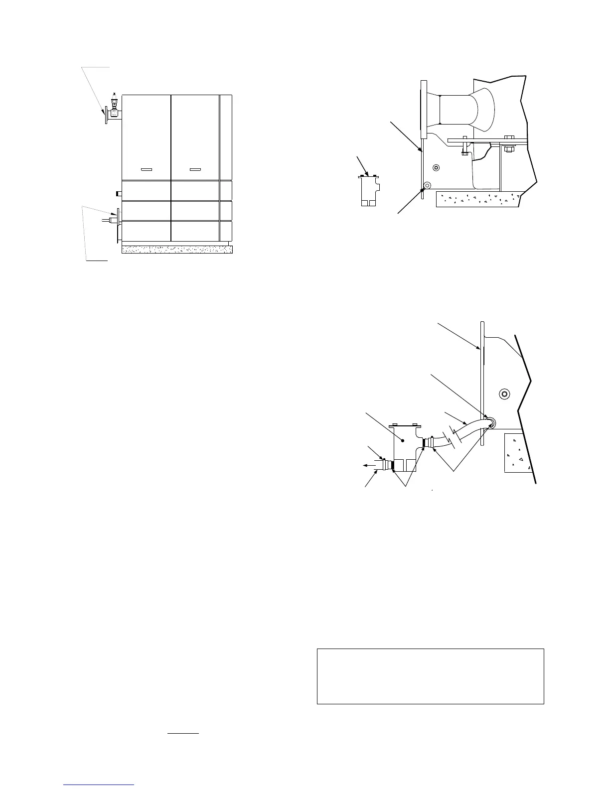
2.3.3 CONDENSATE DRAIN & PIPING
The Benchmark Boiler is designed to condense
water vapor from the flue products. Therefore,
the installation must have provisions for suitable
drainage or collection. A 1/2” NPT drain
connection is provided on the exhaust manifold
(see Fig 2.4). A separate condensate drain trap
(part no. 24060) is shipped loose and must be
installed on the floor behind the unit. Connect
the trap to the exhaust manifold as follows:
1. First, install a 1/2” NPT nipple in the
condensate drain port (Fig. 2.4). Next,
connect a 3/4-to 1/2” reducer to the 1/2”
nipple.
2. On the condensate drain trap, install 3/4”
NPT nipples in the tapped inlet and outlet of
the trap.
3. Attach a length of 1” I.D. polypropylene hose
between the exhaust manifold drain and the
inlet side of the condensate trap (Fig 2.5).
Secure both ends of the hose with clamps.
Drainage from the condensate drain trap
outlet must be by gravity to a nearby floor
drain via a polypropylene hose or suitable
piping.
If a floor drain is not available, a condensate
pump can be used to remove the condensate to
drain. The maximum condensate flow rate is 11
GPH. The condensate drain trap, associated
fittings and drain line must be removable for
routine maintenance. Do Not
hard pipe.
EXHAUST
MANIFOLD
1/2" NPT CONDENSATE
DRAIN CONNECTION
3/4" NPT
CONDENSATE
TRAP
Figure 2.4
Condensate Drain Connection Location
CONDENSATE
TRAP
CLAMPS
CLAMP
TO
FLOOR
DRAIN
1" I.D.
HOSE
1" I.D.
HOSE
3/4" NPT
NIPPLES
CONDENSATE
DRAIN CONNECTION
EXHAUST
MANIFOLD
Figure 2.5
Condensate Trap Installation
2.4. GAS SUPPLY PIPING
The AERCO Gas Fired Equipment Gas
Components and Supply Design Guide (GF-
2030) must be consulted before any gas piping
is designed or started.
WARNING!
DO NOT USE MATCHES, CANDLES,
FLAMES OR OTHER SOURCES OF
IGNITION TO CHECK FOR GAS LEAKS.
 Loading...