SAFETY DEVICE TESTING
6-4
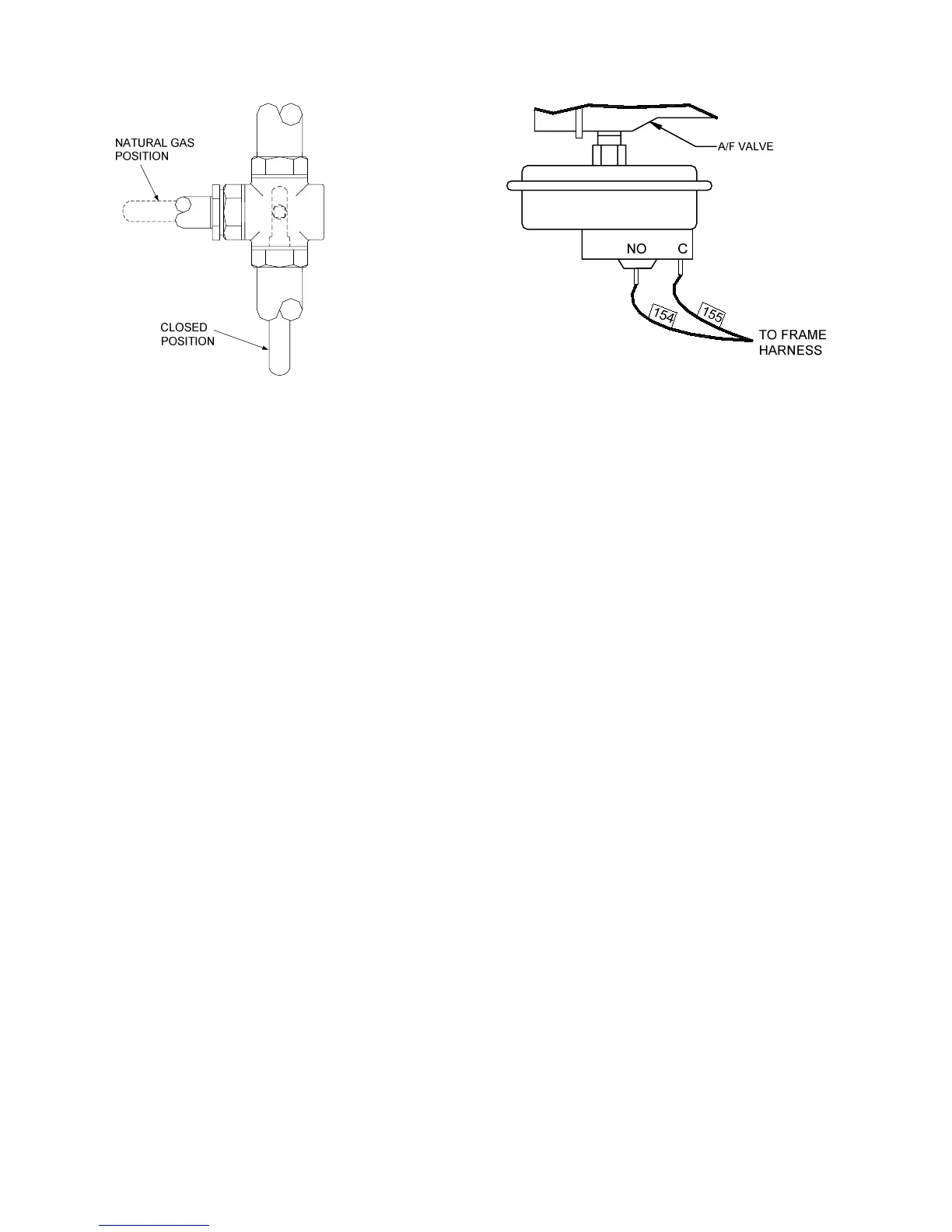
Figure 6.4
Diverter Valve Positions
9. Restart the unit and allow it to prove flame.
10. Once flame is proven, close the manual gas
valve located between the safety shut-off
valve and the differential regulator.
11. For dual fuel units, place the diverter valve in
the closed position (see Fig. 6.4).
12. The unit should shut down and display
FLAME LOSS DURING RUN.
13. Open the valve previously closed in step 10
or 11 and depress the CLEAR button. The
unit should restart and fire.
6.8 AIR FLOW FAULT TEST
1. Start the unit in manual mode and set the
fire rate between 25% and 30%.
2. Once the unit has proved flame, remove
either wire #154 or #155 from the blower
proof switch (see Fig. 6.5) located on the
air/fuel valve.
3. The unit should shut down and display
AIRFLOW FAULT DURING RUN.
4. Replace the wire previously removed from
the blower-proof switch and depress the
CLEAR button. The unit should restart.
Figure 6.5
Blower Proof Switch Location and Wiring
6.9 SSOV PROOF OF CLOSURE
SWITCH
1. Set the unit’s ON/OFF switch to the OFF
position. Place the unit in manual mode and
set the fire rate between 25% and 30%.
2. Remove the Safety Shut-Off Valve (SSOV)
cover (see Fig. 6.6). For units with IRI gas
trains, access the terminals in the
downstream SSOV (see drawing AP-A-742
or AP-A-745 (Dual-Fuel) in Appendix F).
3. Remove either wire #149 or #148 from the
SSOV.
4. The unit should fault and display SSOV
SWITCH OPEN.
5. Replace the wire previously removed and
depress the CLEAR button.
6. Start the unit.
7. Remove the wire again when the unit
reaches the purge cycle.
8. The unit should shut down and display
SSOV FAULT DURING PURGE.
9. Replace the wire on the SSOV and depress
the CLEAR button. The unit should restart.
 Loading...