16
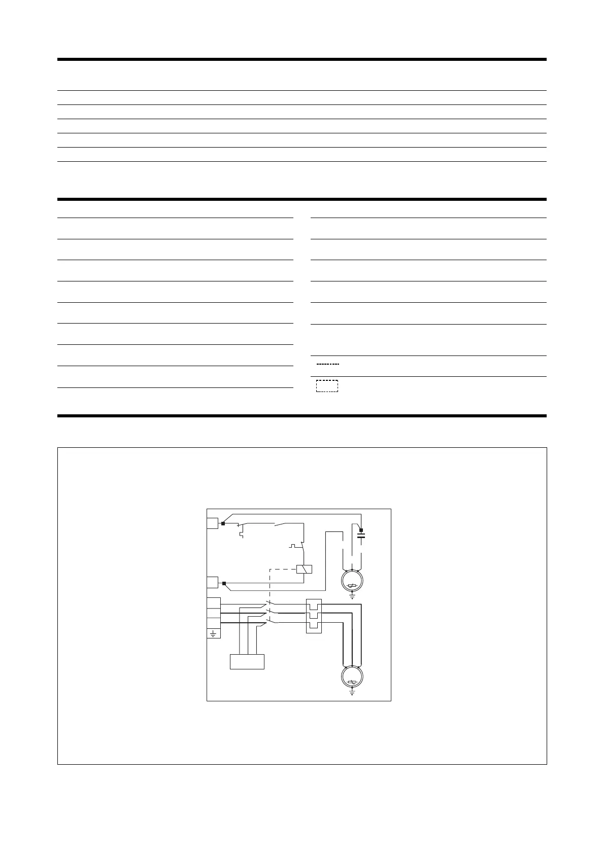
CC = Contattore compressore
Compressor contactor
CMCP = Condensatore di marcia compressore
Compressor running capacitor
CMV = Condensatore di marcia ventilatore
Fan running capacitor
CP = Compressore
Compressor
MV = Motore ventilatore
Fan motor
PT = Protezione motore
Motor protector
RPF = Relè controllo sequenza fasi
Phase sequence control relay
RT = Relè termico
Thermal relay
VI = Valvola inversione ciclo
Reverse cycle valve
IM = Interruttore di linea
Line switch
L = Fase d’alimentazione
Feeding phase
N = Neutro di alimentazione
Feeding neutral
PE = Collegamento di terra
Earth connection
MA = Marrone / Brown
BL = Blu / Blue
NE = Nero / Black
Collegamenti da eseguire in loco
On-site wiring
Componenti non forniti / Components not supplied
LEGENDA PER SCHEMI ELETTRICI • WIRING DIAGRAMS KEY
TAB. F DATI ELETTRICI • ELECTRICAL DATA
CX 1807 T CX 2407 T CX 1807 T CX 2407 T
IM [A]6666
IM 1 [A] - - 2 / 6* 2 / 6*
SEZ. A [mm
2
] 1,5 1,5 1,5 1,5
SEZ. B [mm
2
] - - 2,5 2,5
SEZ. C [mm
2
] 1,5 1,5 1,5 1,5
Gli schemi elettrici sono soggetti ad aggiornamento; è opportuno fare riferimento allo schema elettrico allegato all’apparecchio.
Wiring diagrams may change for updating. It is therefore necessary to refer always to the wiring diagram inside the units.
SCHEMI ELETTRICI • WIRING DIAGRAMS
* = Con accessorio RXCE installato • With RXCE accessory installed
 Loading...