10
Italiano
AGLLRIJ 0907 - 4528560_03
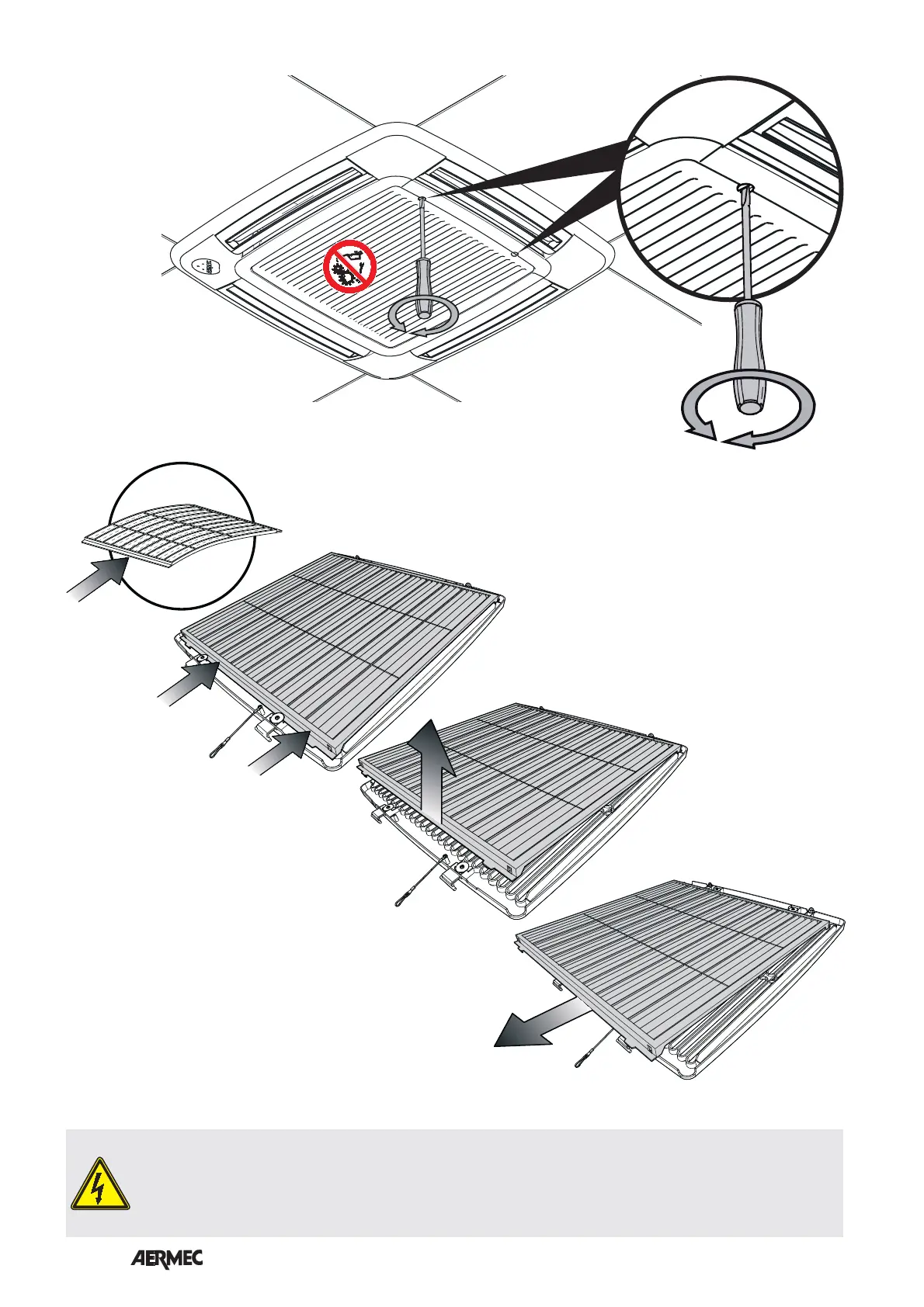
INSTALLAZIONE E SOSTITUZIONE DEL FILTRO "MODULO 840"
PERICOLO: Togliere tensione prima d’iniziare le operazioni di pulizia del filtro e/o dell’unità.
DANGER: Switch off power supply before cleaning filter and/or unit.
DANGER: Couper la tension avant de commencer les opérations de nettoyage du filtre et/ou de l'unité.
GEFAHR: Vor der Reinigung des Filters und/oder des Gerätes die Strom versorgung abschalten.
PELIGRO: Quitar la tensión antes de iniciar las operaciones de limpieza del filtro o de la unidad.