9
Italiano
AGLLRIJ 0907 - 4528560_03
INSTALLAZIONE "GLL20R"
- Aprire l'imballo dell'accessorio assie-
me cornice di mandata e griglia d’aspi-
razione, togliere la griglia dall'imballo
e controllare che non sia stata danneg-
giata durante il trasporto.
- Aprire il coperchio della morsettiera
sulla scatola elettrica, per sbloccare i
ganci a pressione usare un utensile.
- Collegare i cavi di alimentazione alla
morsettiera come indicato nello sche-
ma elettrico.
- Fissare tutti i cavi con il bloccacavo.
- Richiudere il coperchio della morset-
tiera elettrica.
- Verificare ed eventualmente resetta-
re i Dip-Switch sulla scatola elettrica
secondo le funzioni desiderate. (Vedi
tabella delle impostazioni)
- Inserire la scatola elettrica nella guida
dell'unità FCL ed assicurarsi che i con-
nettori siano ben collegati.
- La scatola elettrica va fissata all'unità
FCL con due viti.
- Applicare la sonda aria (SA) al centro
della griglia del ventilatore, fissare il
cavo con le fascette a corredo, stende-
re il cavo in eccesso negli incavi rica-
vati nel polistirolo.
- Collegare la sonda SA al connettore
sulla scatola elettrica.
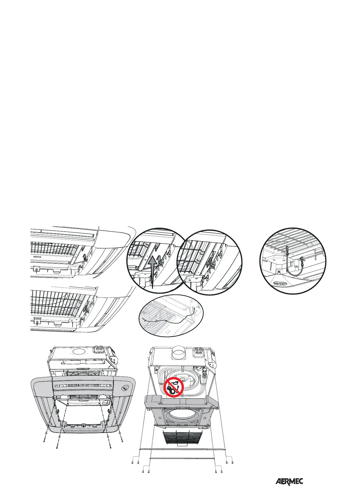
- Togliere la griglia di aspirazione agen-
do sui 2 nottolini ad un ¼ di giro.
- Appendere la cornice ai due ganci di
sostegno, fare attenzione alla posizio-
ne di montaggio, l'angolo della corni-
ce il vetrino con il logo AERMEC deve
coincidere con l'angolo della scatola
elettrica dell'unità FCL.
- ATTENZIONE: fissare un moschetto-
ne del cavetto di sicurezza al tela-
io griglia e l'altro moschettone alla
griglia di protezione del ventilatore.
- Montare l'adattore (a corredo) al cavo
del ricevitore .
- Collegare il cavo di collegamento del
ricevitore al connettore sulla scatola
della scheda elettronica.
- Fissare la cornice all’unità tramite le 4
viti a corredo.
ATTENZIONE!! avvitare le viti con
una coppia di serraggio massima di
0,45 Nm, si consiglia di utilizzare un
cacciavite, non usare avvitatori non
tarati. Una eccessiva coppia di ser-
raggio provoca danni irreversibili alla
bacinella.
La cornice garantisce la tenuta tra aspi-
razione e mandata dell’aria, pertan-
to deve essere fissata correttamente
all’unità senza subire deformazioni.
- Assicurare la griglia di aspirazione al
cavetto di sicurezza.
- Montare la griglia di aspirazione
agganciandola alla cerniera sulla cor-
nice.
- Richiudere la griglia di aspirazione e
avvitare i due nottolini (sul lato oppo-
sto alla cerniera) di un ¼ di giro.
- Registrare la posizione dell’unità dalla
staffa di supporto mediante i dadi, in
modo che l’unità sia in bolla e la cor-
nice appoggi leggermente nel contro-
soffitto.
- Inserire le batterie in dotazione nel
telecomando.
- Avviare il ventilconvettore ed eseguire
una prova di funzionamento, le funzio-
ni sono descritte nel manuale d’uso.
Manutenzione scatola elettrica
In caso si rendesse necessario accedere
alla scatola elettrica per manutenzioni
o per resettare i Dip Switch, seguire le
seguenti indicazioni:
- Aprire la griglia filtro (ruotare i 2 notto-
lini di un ¼ di giro).
- Togliere la vite di bloccaggio dello
sportello d'angolo con il logo Aermec.
- Togliere le 2 viti di bloccaggio della
scatola elettrica.
- Sfilare verso il basso la scatola elettrica.
- Eseguire le manutenzioni necessarie
necessarie.
- Rimontare il tutto seguendo la proce-
dura inversa allo smontaggio.
SA
• Smontaggio per manutenzione
- Prima di eseguire qualsiasi operazione
sull'unità è obbligatorio interrompere
l'alimentazione elettrica.
- Per accedere all'interno dell'unità
rimuovere i due traversini fissati con
le viti al telaio. Sarà quindi possibile
rimuovere la griglia di protezione del
ventilatore e la bacinella in polistirolo.
(vedi figura)
- PERICOLO!!. Prima di ridare tensione
all'unità è obbligatorio aver rimontato
correttamente tutti i componenti ed in
paticolare la griglia di protezione.