15
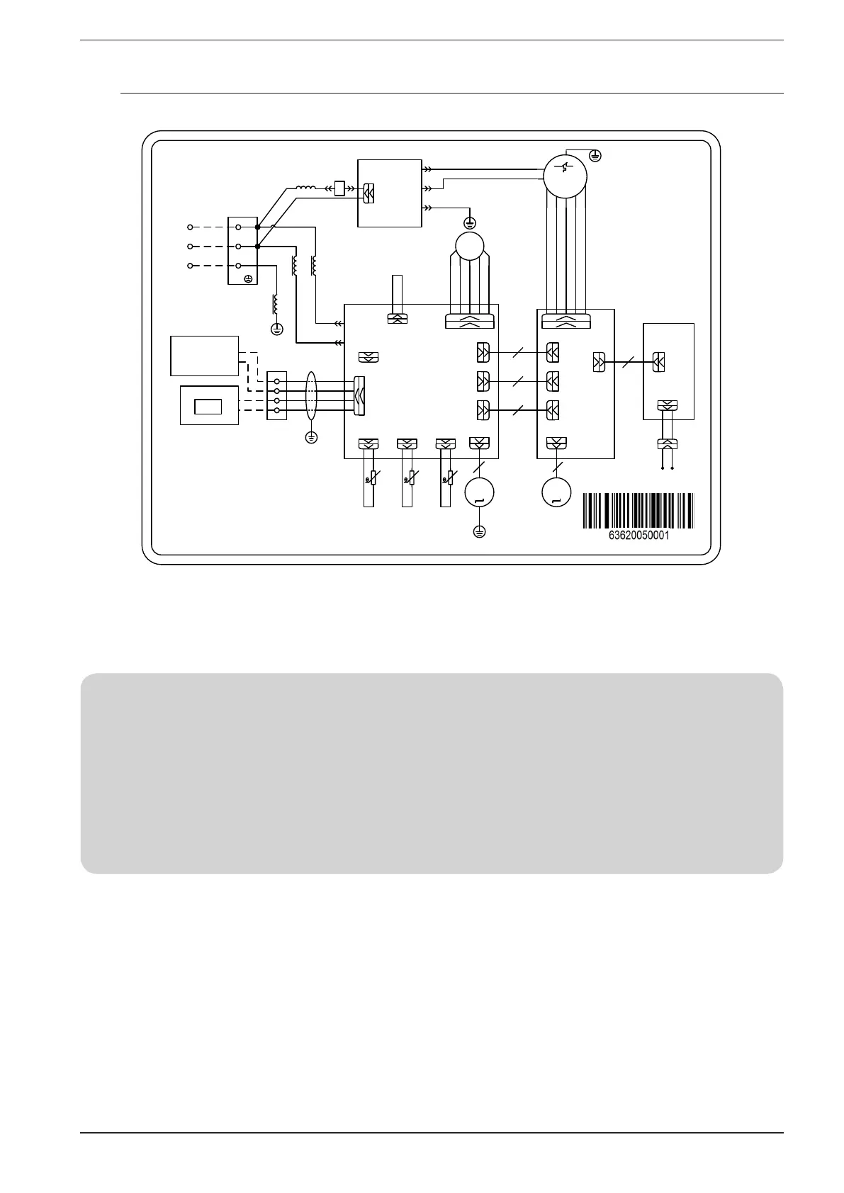
9.3. WIRING DIAGRAM MVA1000V - MVA1400V
POWER
N
L
AP1
MAI N BOARD
N
AC- L
PE
PE
NOUT
LOUT
PE1
CN1
AP2
FI LTER BOARD
~
M1
PE
CN2
CN12
D1
D2
H1
H2
I nt ercommuni cat i on
cor d f or I ndoor
and out door
Wi red cont r ol l er
AP3
LCD
JUMP
EKV
FB( FA)
FB f or el ect r oni c expansi on val ve
wi t h 5 cor es; FA f or el ect r oni c
expansi on val ve wi t h 6 cor es.
CN25
CN28
CN26
15K
RT1
20K
RT2
20K
RT4
ROOM
TUBE- O
TUBE- I
ROOM TEMP.
SENSOR
I NLET PI PE
TEMP. SENSOR
OUTLET PI PE
TEMP. SENSOR
M2
M3
CN22
5
AP4
CONNECTI ON
BOARD
CN22
5
CN11
CN21
CN17
CN21
CN17
CN11
4
6
5
RD
BK
BN
OG
RD
WH
RD
WH
YEGN
CN12
CN12
CN1
BN OG
XT1
XT2
AP5
DI SPLAY
BOARD
I NDOOR UI NT
4
YEGN
RD
BK
PE
RD
BK
BK
BK
WH
The wi r ed cont r ol l er i s
t he opt i onal accessor y.
CAP
CN35
GN
L1
L2
I nduct ance
XT3
BK
RD
1
X1
PE
XT2- H1 XT2- H2
BN OG
For the need of installation refer necessarily to the wiring diagram supplied with the unit. The circuit dia-
gram along with the manuals, must be carefully preserved and made available for future work on the unit.
NOTE IN CONNECTING THE WRC WIRE PANEL
The unit has a display on the machine from which it is possible to set all its functions, however it is also supplied with a WRC wire panel and
a WLRC infrared remote control.
In case you want to use the WRC flush panel to use the unit, you must perform the following procedure:
(1) Physically connect the wire panel to the indoor unit PCB (H1, H2 XT2 terminal board) as indicated in paragraph 9.2;
(2) The alarm message “CP” (control panel conflict) will appear on the display;
(3) While the unit is OFF, press the “Mode” and “Speed” keys simultaneously for 5 seconds to clear the “CP” alarm and enable normal ope-
ration (in this configuration the WRC panel will turn out to be the master compared to the display on the machine);