8
To install the unit you must do the fol-
lowing:
1. Place the unit in the place chosen
for installation (Note: the point of in-
stallation must meet the guidelines
outlined in the chapter concerning
the minimum working also must
comply with all the limitations ex-
pressed in the general instructions);
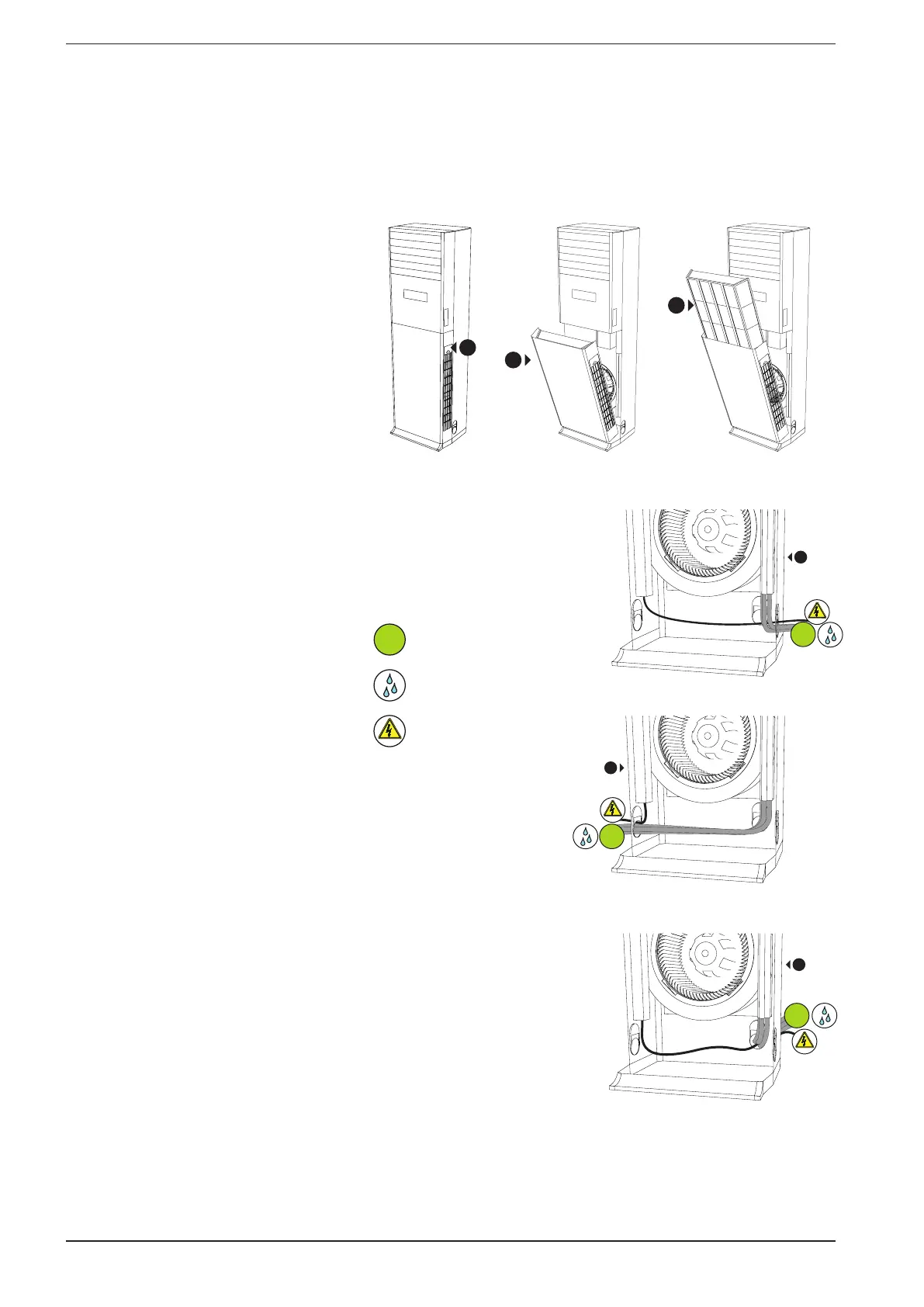
2. Remove the front panel and the
air filter; once you removed you
will have access to the refrigerant
connections and to the electrical
box cover;
3. Remove the electrical box cover to
access the terminals of service ne-
cessary to connect the power sup-
ply, the serial connection and any
panel wire supplied (for more infor-
mation on the electrical connec-
tions, refer to the specific chapter);
Once wired connections, close the
electrical box;
4. Decide which side to pass the refri-
gerant lines, electrical and for the
condensate drain (The unit allows
you to have different configura-
tions as shown in the figure);
5. Execute (as indicated in the spe-
cific chapters) the refrigerant and
water connections;
6. Route the refrigerant lines through
the opening and screw in the dam-
per with the screw (as shown in the
related image);
7. After making all electrical connec-
tions, cooling and hydraulic, fit the
filter and the front panel (simply re-
versing the steps taken to dismantle
them);
8. Fix the anchoring system security
supplied (according to the sequen-
ce shown in the drawings specific);
WARNING: all the cables related to se-
rial links should be kept separate from
the power supply cables to avoid elec-
tromagnetic interference.
7. MECHANICAL INSTALLATION
1
2
3
Procedure to remove the front panel and the air filter:
1. Unscrew the screw on the side air intake.
2. pull the lower part of the body containing the filter.
3. Pull the filter upwards.
Possible configurations for
the passage of the connections:
1. Right side.
2. Left side.
3. Rear.
2
R410A
1
R410A
3
R410A
R410A
refrigerant lines
condensate drain
Power supply
and serial connection