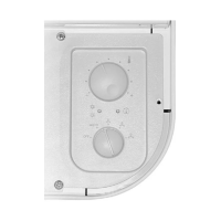
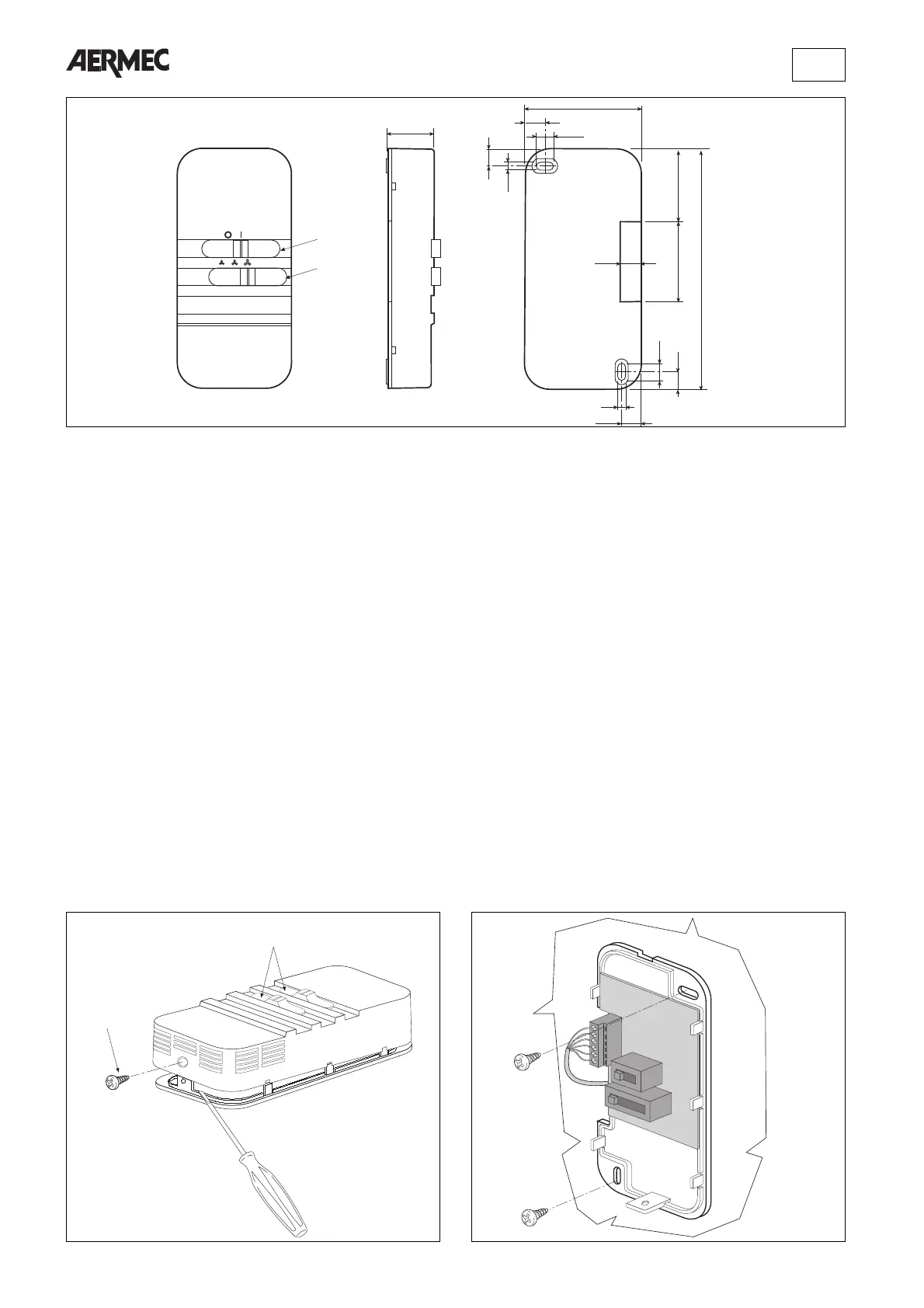
Fig. 4
Fig. 5
FISSAGGIO A PARETE
Per il fissaggio a parete del pannello comandi, procedere
come segue:
– allentare la vite di fissaggio (1 fig 4) ed estrarre l’involucro di
copertura e le leve di commutazione (2);
– scollegare i cavi forniti in dotazione da utilizzare solo in
caso di installazione a bordo macchina;
– fissare a parete il pannello utilizzando gli appositi fori (fig.5);
– introdurre lateralmente il cavetto ed eseguire il cablaggio
con riferimento agli schemi elettrici di figura 10 o 11;
– togliere le leve di commutazione dall’involucro di copertura.
– rimontare l’involucro di copertura ;
– bloccare la vite di fissaggio e riposizionare le leve di com-
mutazione.
WALL MOUNTING
To install the control panel, proceed as follows:
– loosen the screw (1 fig 4), remove the cover and the swit-
ching levers (2);
– disconnect the cables supplied with the unit they should be
used only in case of installation on board of the unit;
– position and secure the panel to the wall by means of the
holes (fig. 5);
– thread the lead through the side, then make wiring connec-
tions (refer to diagrams in figures 10 and 11);
– remove the switching levers from the cover;
– refit the cover;
– tighten the screw, then reposition the switches.
FIXATION SUR PAROI
Pour la fixation du panneau de commande sur paroi, procé-
der comme suit :
– desserrer les vis de fixation (1 fig. 4) et retirer la carrosserie
et les leviers de commutation (2);
– débrancher les câbles fournis de série à utiliser uniquement
en cas d’installation sur appareil;
– fixer le panneau à la paroi en utilisant les trous prévus à cet
effet (fig. 5);
– introduire latéralement le petit câble et effectuer le câblage
en suivant les schémas électriques des fig. 10 ou 11;
– retirer les leviers de commutation de la carrosserie;
– remonter la carrosserie;
– bloquer les vis de fixation et repositionner les leviers de
commutation.
WANDBEFESTIGUNG
Für die Wandbefestigung der Fernbedienung wie folgt verfah-
ren:
– die Befestigungsschraube (1 Abb. 4) lockern, das Gehäuse
und die Umschalthebel (2) abnehmen;
– Die mitgelieferten Kabel abnehmen; diese sind nur bei der
Installation an der Maschine zu benutzen;
– die Fernbedienung mit Hilfe der vorgesehenen Bohrungen
(Abb. 5) an der Wand befestigen;
– das Kabel seitlich einführen und die Verkabelung gemäß
den Schaltplänen aus Abbildung 10 oder 11 ausführen;
– die Umschalthebel vom Gehäuse abnehmen.
– das Gehäuse wieder montieren;
– die Befestigungsschraube festziehen und die Umschalthebel
wieder einsetzen.
 Loading...