I dati tecnici riportati nella presente documentazione non sono impegnativi.
La AERMEC S.p.A. si riserva la facoltà di apportare in qualsiasi momento tutte le
modifiche ritenute necessarie per il miglioramento del prodotto.
Technical data shown in this booklet are not binding.
AERMEC S.p.A. shall have the right to introduce at any time whatever modifications
deemed necessary to the improvement of the product.
Les données mentionnées dans ce manuel ne constituent aucun engagement de notre
part. AERMEC S.p.A. se réserve le droit de modifier à tous moments les données con-
sidérées nécessaires à l' amelioration du produit.
Im Sinne des technischen Fortschrittes behält sich AERMEC S.p.A. vor, in der
Produktion Änderungen und Verbesserungen ohne Ankündigung durchzuführen.
4
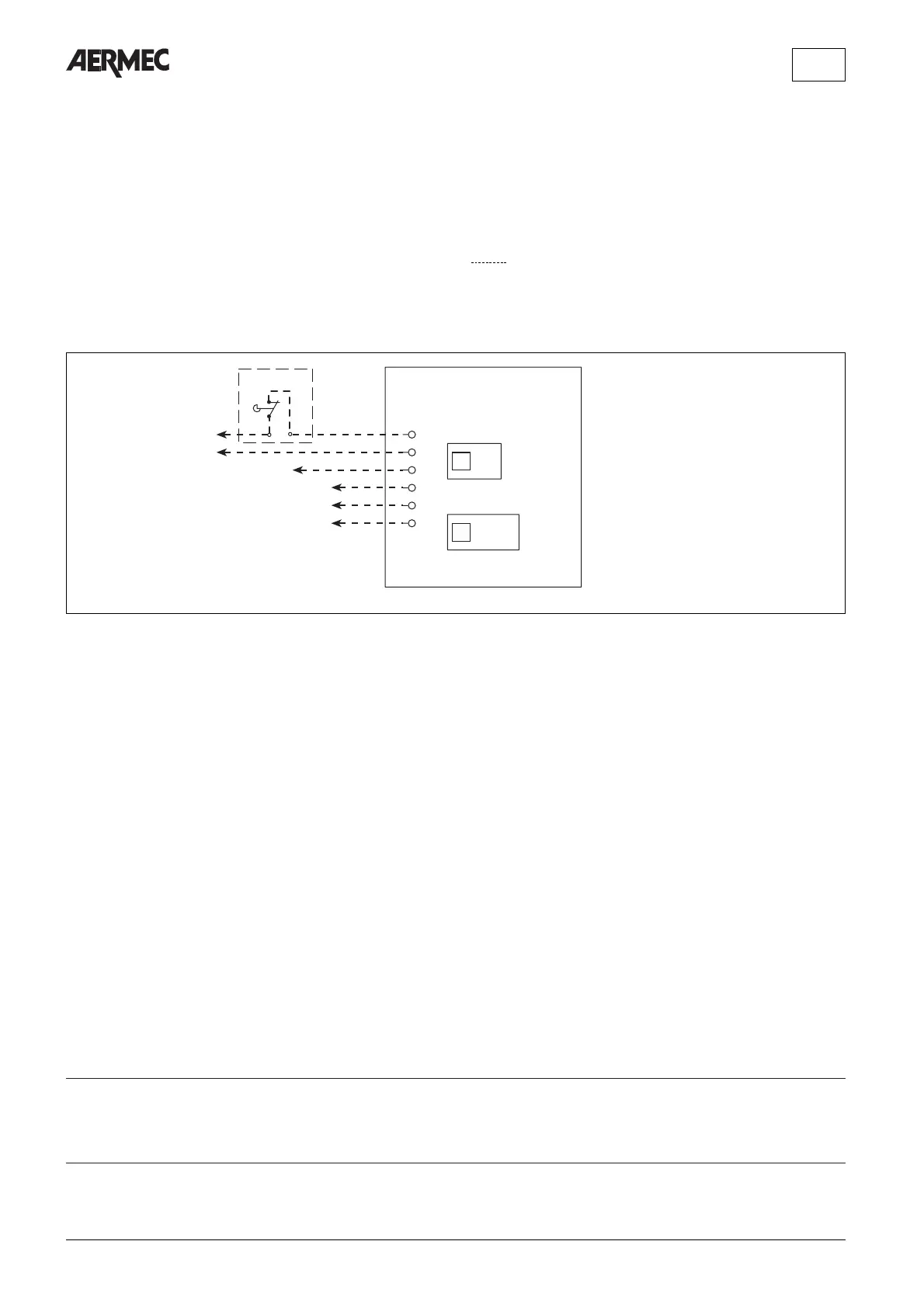
PX2
1
2
3
4
5
6
01
1 23
L
N
MV (Min)
MV (Med)
MV (Max)
MV
MS
Fig. 9
MS = Microinterruttore griglia (FCX U - OMNIA)
Louvre microswitch (FCX U - OMNIA)
Micro-interrupteur grille (FCX U - OMNIA)
Mikroschalter Gitter (FCX U - OMNIA)
MV = Motore ventilatore
Fan motor
Moteur ventilateur
Ventilatormotor
PX2 = Scheda di controllo
Electronic control board
Platine de contrôle
Steuerschaltkreis
= Collegamenti a cura dell’installatore
Connections to be made by installeur
Branchements aux bons soins de l’installateur
Bauseitig durchzuführende verdrahtung
Per il montaggio a bordo macchina i collegamenti sono forniti a corredo.
Connectors for on-board assembly are supplied as standard equipment.
Pour le montage sur l’appareil, les raccordements sont fournis avec l’appareil.
Für die Montage am Gerät sind die Anschlusskabeln mitgeliefert.
LEGENDA • READING KEY • LEGENDE • LEGENDE
Gli schemi elettrici sono soggetti ad aggiornamento; è opportuno fare riferimento allo schema elettrico allegato all' apparecchio.
Wiring diagrams may change for updating. It is therefore necessary to refer always to the wiring diagram inside the units.
Les schémas électriques peuvent être modifies en conséquence des mises à jour. Il faut toujours se référer aux schémas électriques dans les appareils.
Die Schaltschemas können geändert werden; es empfiehlt sich immer auf das mit dem Zubehör verpackte El. Schaltschema zu beziehen.
SCHEMI ELETTRICI • WIRING DIAGRAMS • SCHEMAS ELECTRIQUES • SCHALTPLANE
AERMEC S.p.A.
I-37040 Bevilacqua (VR) - Italia
Via Roma, 44 - Tel. (+39) 0442 633111
Telefax (+39) 0442 93730 - (+39) 0442 93566
 Loading...