17
TA 24 4R
Description
Notes
Accessory
Air ow rate
m
3
/h 800 1200 1600 2000 2400
Intake grid GAP Pa -3 -7 -11 -17 -24
Anti-freeze damper SAP Pa -1 -1 -2 -4 -5
Intake silencers SSL Pa -3 -6 -10 -16 -22
Return fan VRF Pa 326 349 347 320 268
Mixing chamber with 3 dampers M3S Pa -1 -2 -4 -6 -8
Mixing chamber with 2 dampers M2S Pa -1 -1 -2 -4 -5
Mixing chamber with 2 front dampers S2Z Pa -2 -3 -6 -9 -12
∆ pressure drops between the 4R and 6R coil
Pa -1 -3 -5 -6 -9
2R Water post-heating coil 2RPR Pa -5 -10 -17 -25 -35
1R Water post-heating coil 1RPR Pa -2 -5 -8 -12 -17
Electric Post -Heating Coil PBE Pa -1 -2 -3 -4 -5
Silencers
SSL Pa -3 -6 -10 -16 -22
•Soft bag lters, FTF Pa -6 -12 -21 -31 -43
Closed ow plenum PMC Pa 0 0 0 0 0
Flow plenum with circular vents PMM Pa 0 -1 -2 -2 -3
Flow damper SAP Pa -1 -1 -2 -4 -5
Flow grid GMD Pa -1 -1 -2 -4 -5
X Version (without coil)
Pa 4 8 14 22 30
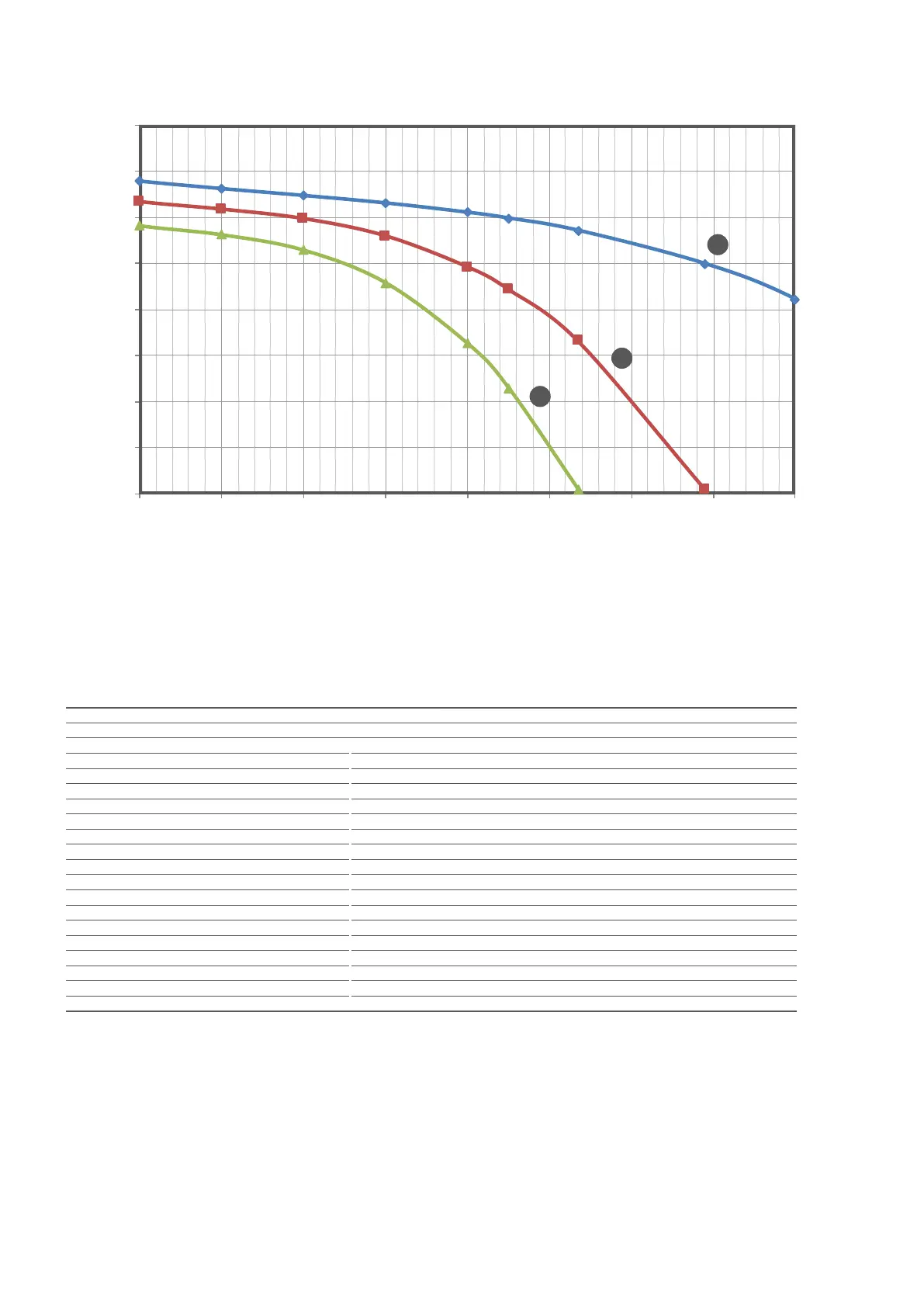
H Maximum speed; M Average speed; L Minimum speed
Air ow rate
(m
3
/h)
Useful static pressure (Pa)
400
350
0
50
100
150
200
250
300
800 1000 1200 1400 1600 1800 2000 2200 2400
L
M
H