19
C/FC VC/FVCC/FC VC/FVCSAVC/FVCSA
VC/FSA
C/F
VC/FSA
C/F
SA
C/F
SA
SW
VC/FVCSA SW VC/FVCSA C/FC
SW VC/F
C/F
VC/FSA SW
C/F
SA SW
C/F
SW
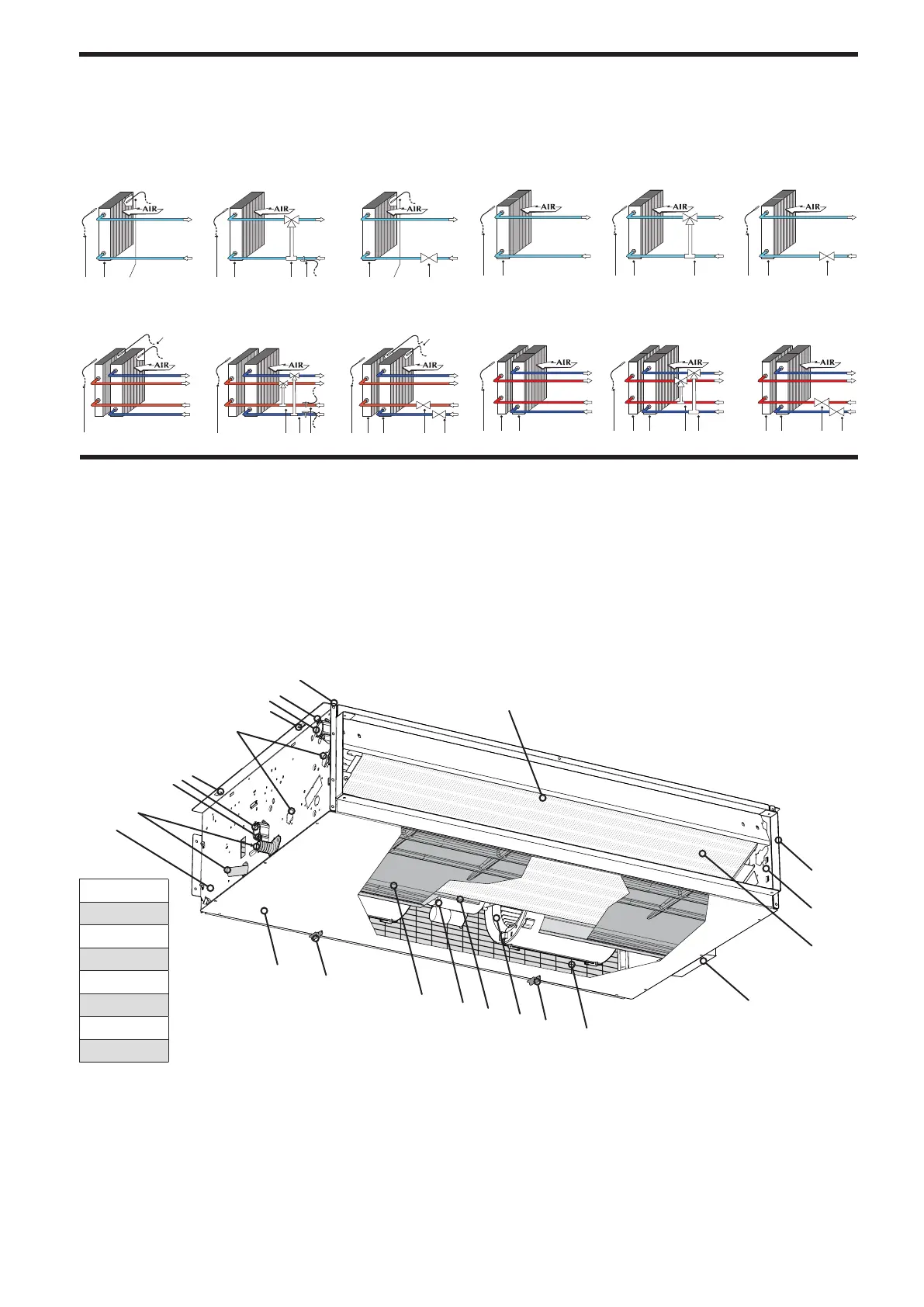
2 pipe system with water sensor
SW Water temperature sensor
VC/F Valve (Heat / Cool)
VC Valve (Heat)
SA Ambient temperature sensor
C/F Coil (Heat / Cool)
C Coil (Heat)
SYSTEM EXAMPLES
2 pipe system without water sensor
4 pipe system with water sensor 4 pipe system without water sensor
Legend:
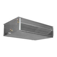
MAIN COMPONENTS
1 Discharge air
2 Frame
3 Vent / drain on coil
4 Hydraulic connections (water outlet)
5 Mounting slot
6 Holes for heat exchanger coil
7 Hydraulic connections (water inlet)
8 Water discharge of exchanger coil
9 Condensate discharge
10 Left side (load bearing
11 Front panel enclosure (lower)
12 Filter lock
13 Condensate drain tray
14 Electric motor
15 Electrical box of electric motor
16 Centrifugal fan
17 Air filter (intake)
18 Electrical box
19 Exchanger coil
20 Right side (load bearing)
21 Discharge air flange
VES 030
VES 040
VES 130
VES 140
VES 230
VES 240
VES 330
VES 340
2
3
1
4
6
17
13
11
14
15
16
10
11
5
7
8
9
18
19
12
5
20
21