8
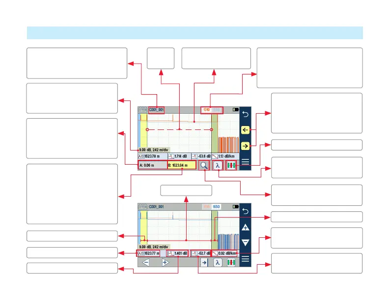
Expert and Real Time OTDR: Trace Display
Grid units display dB/div on
vertical axis and distance/div
on horizontal axis
File name: consists of cable
name and ber number, or “New
Trace” if le has not been saved
White background indicates
the currently selected (active)
wavelength. Cursor measurements
apply to active wavelength.
1310 nm trace is red;
1550 nm trace is blue
Receive cable (if present)
Launch cable (if present)
B cursor location (B is active).
• Yellow highlight indicates
the currently active cursor
• Touch the screen where
you want to reposition the
currently active cursor
Used for cursor position and
ne adjustments. Touch or
touch and hold arrows to
move the active cursor.
A cursor location (A is
inactive cursor). Touch non-
highlighted cursor box to
make the A cursor active.
Loss between A and B cursor
Loss-per-distance between A
and B cursors
Maximum Reectance
between A and B cursor
Touch to toggle active traces
(for multi-wavelength tests)
Distance from A to B cursor
Touch to enable and display
‘zoom control’ mode
Fiber under test
Touch to select LinkMap view
A and B
cursors
 Loading...