27
Connecting To Gas
The cooker must be installed by connection to rigid
pipework, which should not be less than 15 mm diameter.
Connection is made to the 15 mm compression tting
located just below the hotplate level on the rear left hand
side of the cooker.
1. Mark o approximate position on wall for gas supply to
cooker (See Specication).
2. Isolate the gas supply and connect pipework as required
up to the position marked.
3. Check for gas tightness after connecting the gas supply.
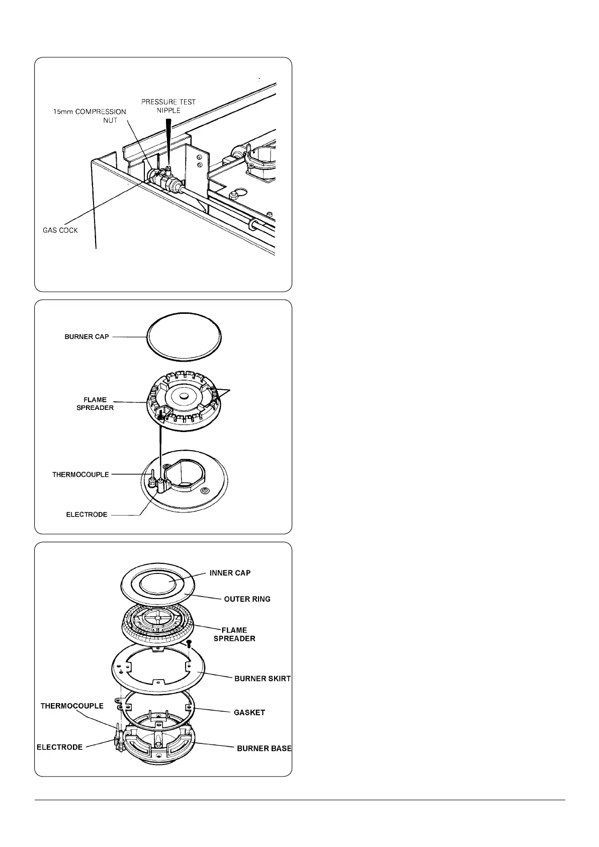
4. Make nal gas connection to the cooker (15 mm
compression) into the combined gas cock/pressure test
tting (See Fig. 11.6).
5. Check for gas tightness after connecting the gas supply.
Pressure Testing
The pressure test point is situated at the rear left hand side of
the appliance just below hotplate level. (Fig. 11.6).
1. Remove screw from pressure test nipple. Fit the pressure
gauge onto the pressure test nipple.
2. Turn the gas cock to the ON position.
3. Place one of the burner heads and burner cap into
position on the burner body. Push in and turn the
appropriate control knob anti-clockwise to full-on
position, and light the burner with a match.
4. For Natural Gas appliance, the pressure should be
nominal 20mbar (8 inches water gauge).
5. For LPG appliance (propane) the pressure should be
nominal 37mbar (14.8 inches water gauge).
6. Turn o the tap, turn o gas cock, disconnect the
pressure gauge and ret pressure test screw to pressure
test nipple.
7. Turn the gas cock back to the ON position.
8. Check for gas tightness.
Fig. 11.6
DESN 516858
DESN 513513
Fig. 11.7
BURNER CAP
RETAINING
LUGS
Fig. 11.8
DESN 513898