28
Final Fitting
1. Apply tape (provided) to the underside of the lap strip
on the Module top plate.
2. Replace module hotplate. Reassemble in reverse order
and reconnect top plate wiring harnesses into snap in
connectors mounted in chassis. Ensure burner heads
and burner caps are correctly located (See Fig. 11.7 and
Fig. 11.8), and electrodes are not damaged.
3. Replace Module top plate as follows:-
4. Support top plate at front and reconnect the Earth and
wiring to the two neons.
5. Carefully lower the top plate into position taking care
not to damage wiring or neons.
6. Ensure holes for control spindles are aligned correctly,
and replace 2 screws into control panel.
7. Loosely screw the top plate down with 4 retaining
screws.
8. Verify that the two top plates are level and proceed with
tightening down.
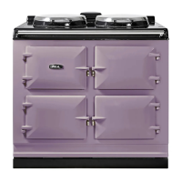
9. Fit the Module handrail bracket over the xing
stud located on the top plate. Lock into position by
tightening the grub screw nearest the appliance. (See
Fig. 11.9).
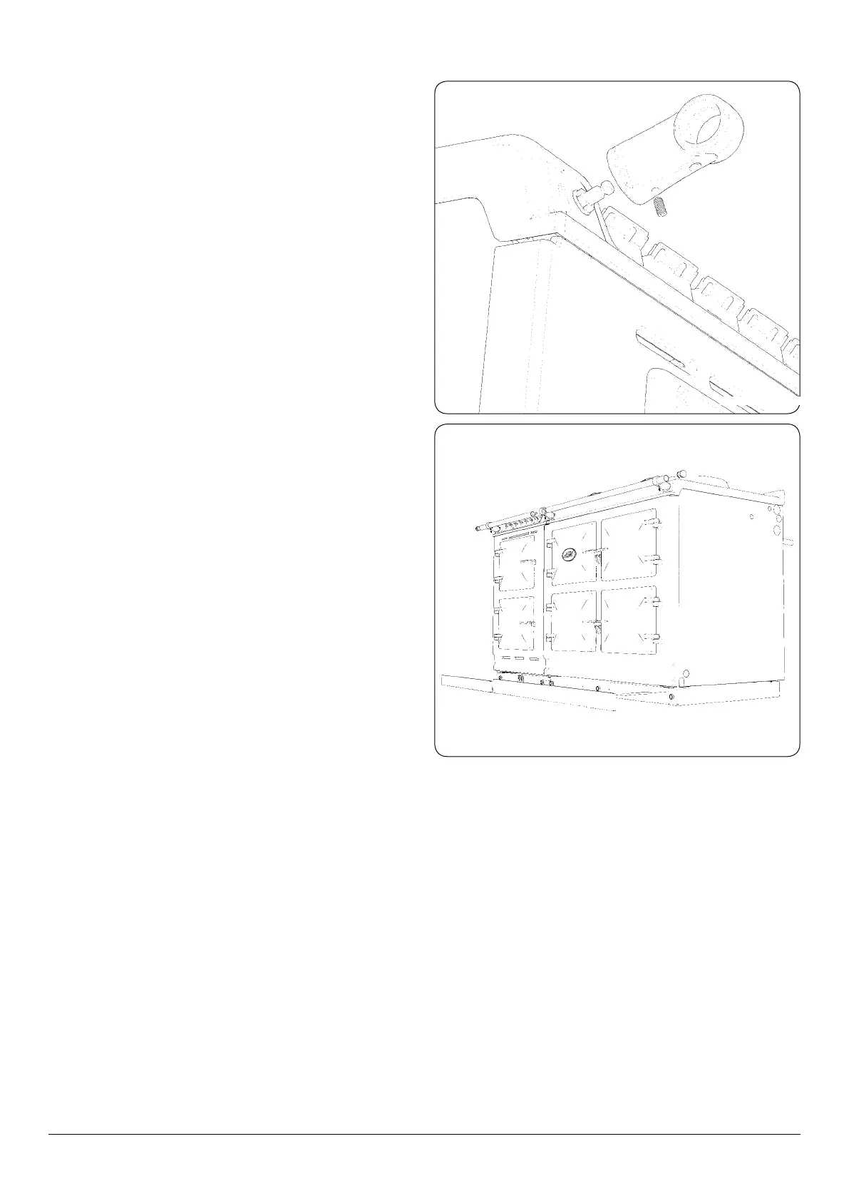
10. Next, t all thread stud into the insert located in the
one end of the Module handrail, then feed the handrail
through the bracket and screw the handrails together.
(See Fig. 11.10).
11. Once the handrail assembly is located squarely, lock the
handrail in position by winding in the grub screws on
the underside of each handrail bracket.
12. Once the handrails are locked in position, t the
handrail endcaps. The endcaps should be carefully
pushed into place until they sit ush with the outside
face of each bracket (a light smear of lubricant such as,
washing up liquid on the end cap ‘O’ rings may ease
tment).
13. Finally, t the plinth facia to the magnets on the front of
the plinth, making sure that the right hand side of the
Module plinth facia sits against the left hand side of the
AGA R7/eR7 plinth facia leaving no gap between. Also
make sure that the plinth facias are centrally located
and do not overhang either appliance (See Fig. 11.10).
14. Commission the AGA R7/eR7, as stated in the relevant
Installation Instructions and carry out functional test on
each of the features of the Module.
DESN 516855
Fig. 11.9
Fig. 11.10
DESN 516856