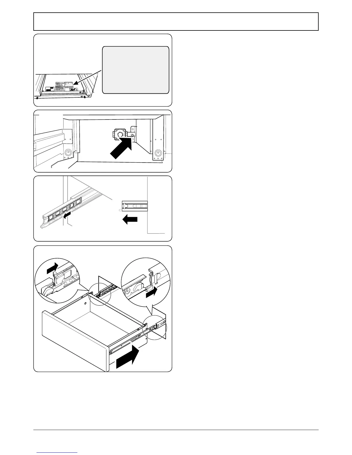
Stick on Labels
Complete the conversion label (kit number A060048) and
stick it next to the ratings label inside the drawer cavity to
indicate the gas the appliance is now set for (Fig. 13.12).
Also, stick the “NOW ADJUSTED FOR LP GAS” label in a
similar position.
Pressure Testing
Connect the appliance to the gas supply. Check the appliance
is gas sound.
The gas pressure can be measured at the pressure test point
on the appliance side of the pressure regulator (Fig. 13.13).
For proper operation, the pressure of LP supplied to the
regulator must be between 10’’ and 13’’ of water column
(2.49 – 3.24 kPa).
When checking for proper operation of the regulator, the
inlet pressure must be at least 1’’ (0.25 kPa) greater than the
operating (manifold) pressure as given above.
The pressure regulator located at the inlet of the range
manifold must remain in the supply line regardless of
whether natural or LP gas is being used.
The pressure with at least 2 surface burners operating should
be 10° WC for Propane gas.
Fitting the Drawer
NOTE: To avoid exterior damage to the storage drawer. Place
a soft cushioned mat on the oor.
1. To t the drawer, pull the side rails fully out (Fig. 13.14).
2. Carefully move the drawer back between the rails and
rest it on the side rails.
3. At each side, hold the front of the drawer and pull the
side rail forward so that the clips click into position,
holding the drawer to the side rails (Fig. 13.15).
n
Check the appliance is gas sound.
n
DO NOT use a ame to check for gas leaks.
When using test pressures greater than ½ psi (3.5 kPa)
to pressure test the gas supply system of the residence,
disconnect the range and individual shut-o valve from the
gas supply piping.
When using test pressures of ½ psi
(3.5 kPa) or less to test
the gas supply system, simply isolate the range from the gas
supply system by closing the individual shut-o valve.
n
Check the operation of all the burners.
Fig. 13.12
Make sure the inner
rail is pulled forwards
Fig. 13.13
Fig. 13.14
Fig. 13.15