166
Chapter 3 Features and Functions
Triggering
3
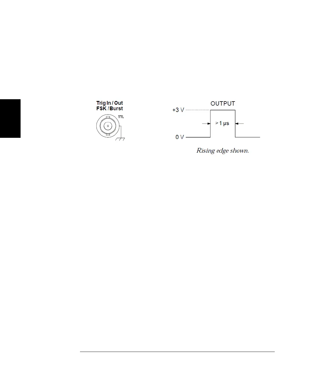
Trigger Output Signal
A “trigger out” signal is provided on the rear-panel Trig Out connector
(used with sweep and burst only). When enabled, a TTL-compatible
square waveform
with either a rising edge (default) or falling edge is
output from the rear-panel
Trig Out
connector
at the beginning of the
sweep or burst.
• When the Internal (immediate) trigger source or Timer is selected,
the waveform generator outputs a square waveform with a 50% duty
cycle from the Trig Out connector at the beginning of the sweep or
burst. The period of the waveform is equal to the specified sweep time
or burst period.
• When the External trigger source is selected, the waveform generator
automatically disables the “trigger out” signal. The
Trig Out
connector
cannot be used for both operations at the same time (an externally-
triggered waveform uses the same connector to trigger the sweep
or burst).
• When the Bus (software) or manual trigger source is selected, the
waveform generator outputs a pulse (>1 µs pulse width) from the Trig
Out connector at the beginning of each sweep or burst.
• Front-Panel Operation: After enabling sweeps or burst, press
Trig Out Setup. Then select the desired edge by pressing Trig Out.
• Remote Interface Operation:
OUTPut:TRIGger:SLOPe {POSitive|NEGative}
OUTPut:TRIGger {OFF|ON}
 Loading...