Chapter 3 Disassembly/Assembly Procedures and Parts List 47
Inguard Logic assembly to the Inguard Power Supply assembly.
Unplug this cable at the A/D Converter and Inguard Logic assembly.
4. Locate the grey 20-pin cable that connects the A/D Converter and
Inguard Logic assembly to the DC Circuitry assembly. Unplug this
cable at the A/D Converter and Inguard Logic assembly.
5. Unplug both sets (four cables) of the blue and grey fiber optic cables
that connect the A/D Converter and Inguard Logic assembly to the
Outguard Power Supply assembly.
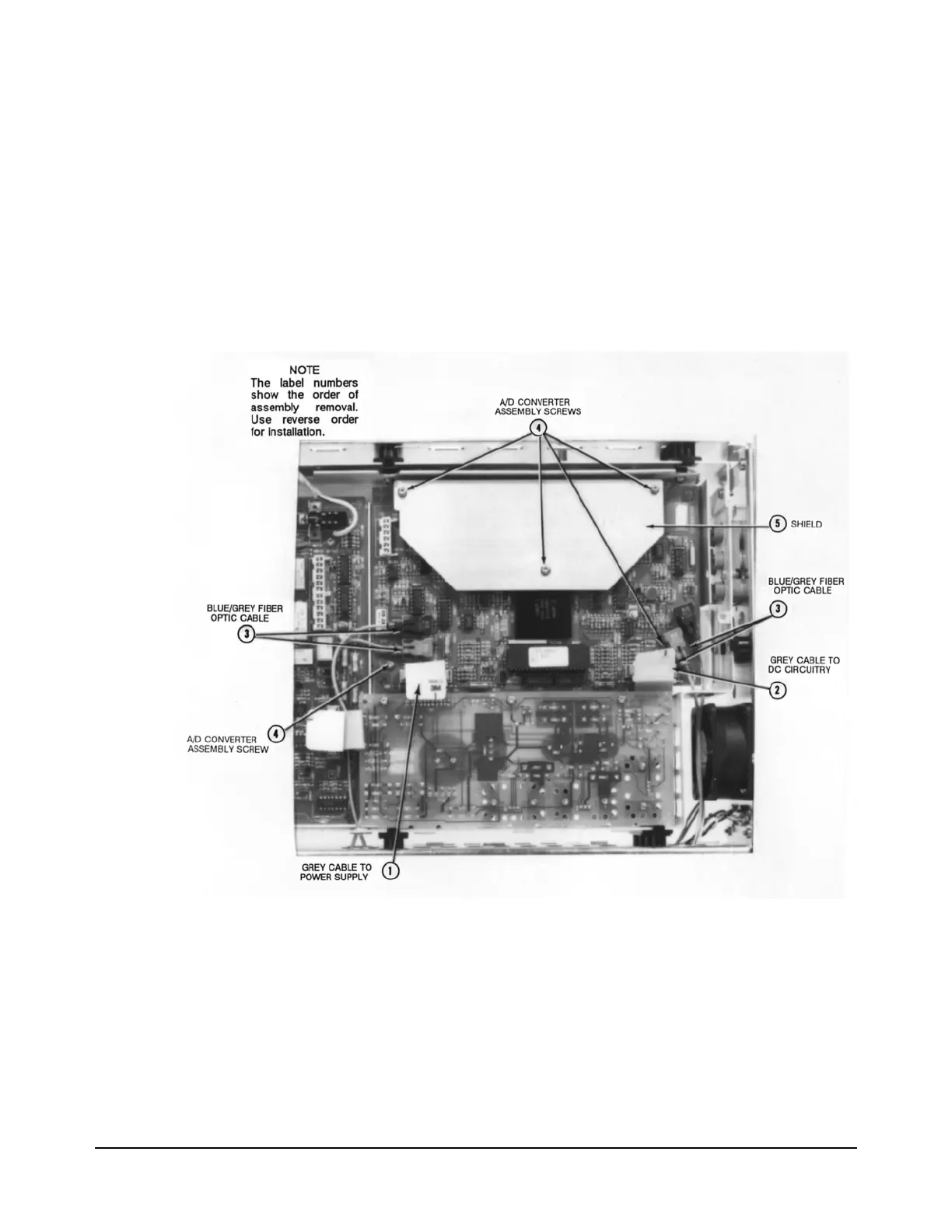
Figure 16. A/D Converter and Inguard Logic Assembly
6. Use the #TX10 Torx driver to remove the three screws on the shield
and the two screws on the A/D Converter and Inguard Logic assembly.
Then remove the shield.
7. Unplug and remove the A/D Converter and Inguard Logic board from
the inguard chassis.
Installation Procedure 1. Line up the A/D Converter and Inguard Logic board with the

 Loading...


