48 Chapter 3 Disassembly/Assembly Procedures and Parts List
connector in the inguard chassis. Then plug the board all the way into
the connector.
2. Place the A/D Converter and Inguard Logic shield on the board. Then
use the #TX10 Torx driver to install the three screws on the shield.
3. Locate the grey 20-pin cable connected to the Inguard Power Supply
assembly. Line up the cable plug with the corresponding socket on the
A/D Converter and Inguard Logic assembly. Then plug the cable all
the way in.
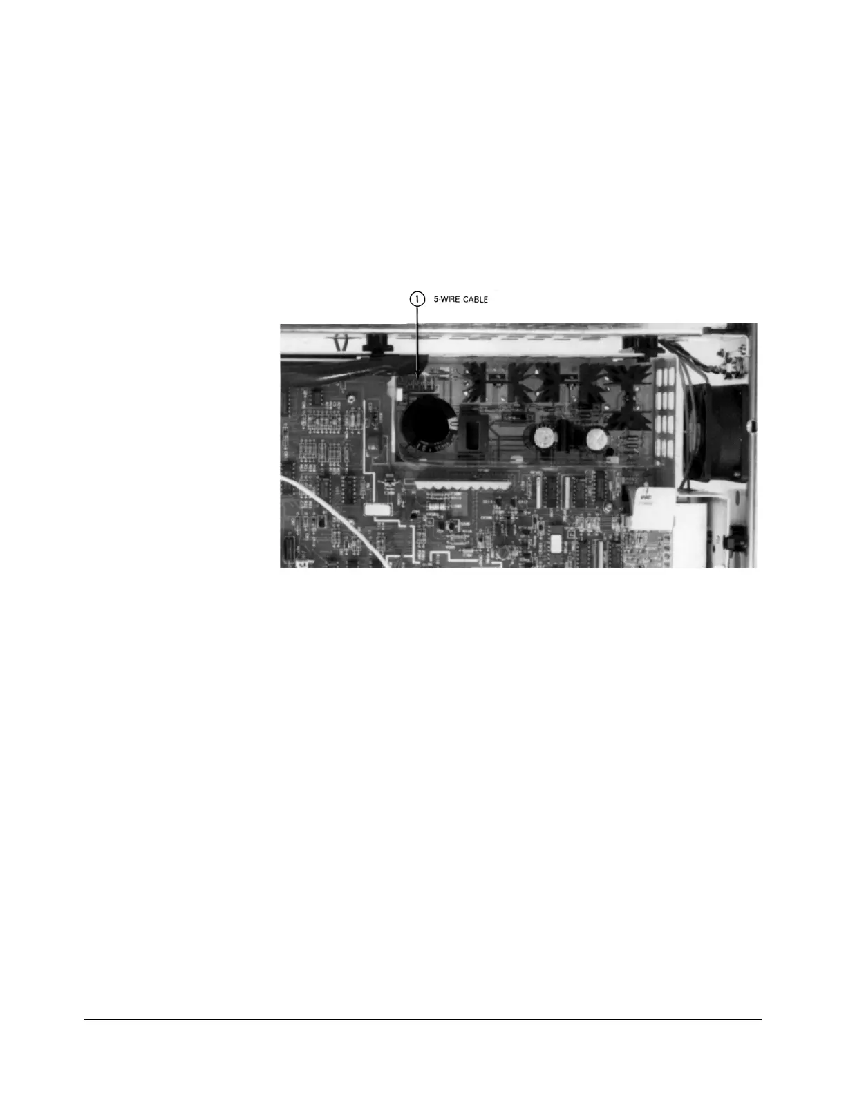
Figure 17. Remove/Install Transformer Cable on Inguard Power Supply
4. Locate the grey 20-pin cable connected to the DC Circuitry assembly.
Line up the cable plug with the corresponding socket on the A/D
Converter and Inguard Logic assembly. Then plug the cable all the
way in.
5. Plug in both sets of the blue and grey fiber optic cables into the
corresponding sockets on the A/D Converter and Inguard Logic
assembly.
6. Use the Covers Installation Procedure in this section of the manual to
install the 3458A bottom cover and bottom shield.
NOTE
The label numbers in
Figures 16 and 17
show the order
assembly removal.
Use reverse order
for installation.

 Loading...


