50 Chapter 3 Disassembly/Assembly Procedures and Parts List
Installation Procedure 1. Set the 3458A on your workbench with the bottom facing you.
2. Refer to Figure 18. Line up the Inguard Power Supply assembly with
the slots in the chassis. Then push the board in.
3. Use the #TX10 Torx driver to install the three screws on the Inguard
Power Supply board.
4. Locate the grey 20-pin cable connected to the AC Converter assembly.
Line up the cable plug with the socket on the AC Converter assembly.
Then plug the cable all the way in.
5. Locate the grey 20-pin cable connected to the A/D Converter and
Inguard Logic assembly. Line up the cable plug with the socket on the
A/D Converter and Inguard Logic assembly. Then plug the cable all
the way in.
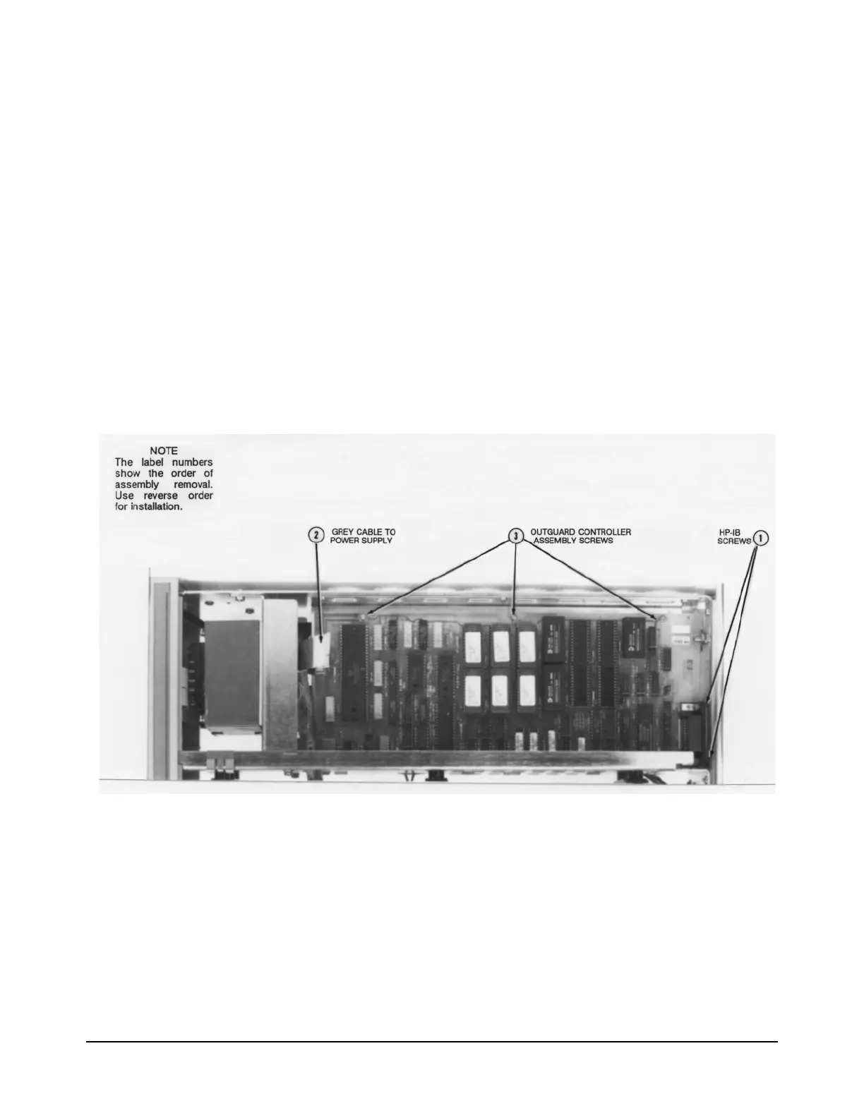
Figure 19. Outguard Controller Assembly Removal/Installation
6. Set the 3458A on your workbench with the top facing you.
7. Refer to Figure 17. Locate the cable connected to the power
transformer. Line up the cable plug with the socket on the Inguard
Power Supply assembly. Then plug the cable in.
8. Use the Covers Installation Procedure in this section of the manual to
install the 3458A top/bottom covers and top/bottom shields.

 Loading...


