62 Chapter 3 Disassembly/Assembly Procedures and Parts List
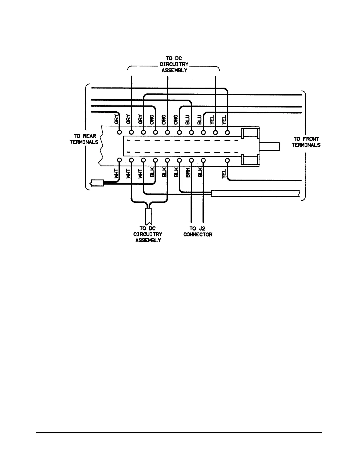
Figure 27. Wire/Cable Locations on Front/Rear Terminals Switch
4. Use the #TX10 Torx driver to remove the four screws from the
Front/Rear Terminals switch assembly.
5. On the Front/Rear Terminals switch assembly, note for future
reference the location of the wires connected to the assembly. These
locations are also shown in Figure 27. Then unplug and lay aside all
wires from the assembly.
Installation Procedure 1. Refer to Figure 27. Plug in all wires to the Front/Rear Terminals
switch assembly. Use the wire locations noted in the previous
procedure.
2. Line up the mounting holes of the assembly with the standoffs on the
inguard chassis. Use the #TX10 Torx driver to install the four screws
on the assembly.
3. Guide the Front/Rear Terminals switch pushrod through the rear of the
front panel's access hole. Then align the pushrod with the Front/Rear
Terminals switch shaft and push it all the way onto the shaft.

 Loading...


