Note
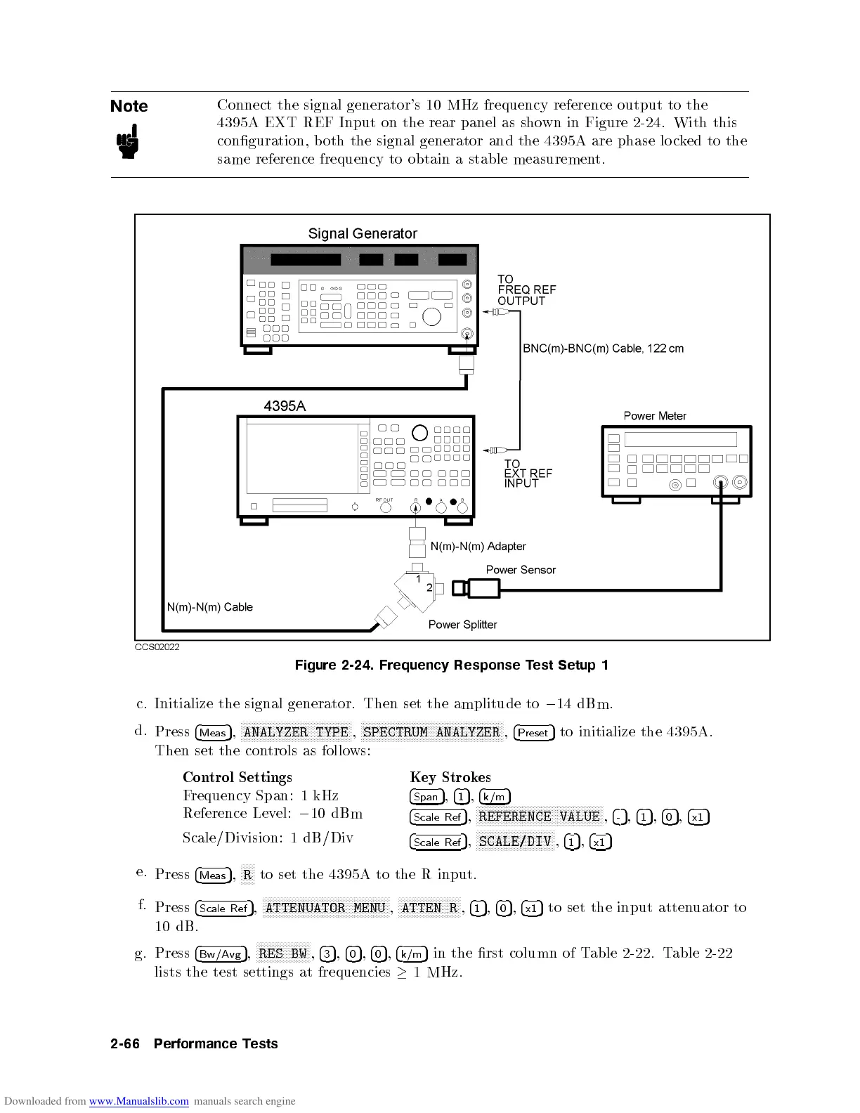
Connect
the signal
generator's 10
MHz frequency
reference
output
to
the
4395A
EXT
REF
Input
on
the rear
panel as
shown
in Figure
2-24.
With this
conguration, b
oth the
signal generator
and the
4395A are
phase
lo
c
k
ed
to
the
same
reference
frequency
to
obtain
a
stable
measuremen
t.
Figure
2-24.
Frequency Response
Test
Setup 1
c.
Initialize
the
signal
generator.
Then set
the amplitude
to
0
14 dBm.
d.
Press
4
Meas
5
,
NN
NN
NN
N
N
N
N
N
N
N
N
N
N
N
N
N
N
N
N
N
NN
NN
NN
NN
N
N
N
N
N
N
N
N
N
N
ANALYZER
TYPE
,
NN
NN
NN
N
N
N
N
N
N
N
N
N
N
N
N
N
N
N
N
N
NN
NN
NN
NN
N
N
N
N
N
N
N
N
N
N
N
N
N
N
N
N
N
NN
NN
N
SPECTRUM
ANALYZER
,
4
Preset
5
to
initialize
the
4395A
.
Then
set
the
con
trols
as
follows:
Control
Settings Key Strokes
Frequency Span: 1 kHz
4
Span
5
,
4
1
5
,
4
k/m
5
Reference Lev
el:
0
10 dBm
4
Scale Ref
5
,
NNNNNNNNNNNNNNNNN
NNNNNNNNNNNNNNNNNNNNNNNNN
NNNNN
REFERENCE VALUE
,
4
-
5
,
4
1
5
,
4
0
5
,
4
x1
5
Scale/Division: 1 dB/Div
4
Scale Ref
5
,
NN
NNNNNNNNNNNNNNNNNNNNNNNNN
NN
SCALE/DIV
,
4
1
5
,
4
x1
5
e.
Press
4
Meas
5
,
NNNNN
R
to set the 4395A to the R input.
f.
Press
4
Scale Ref
5
,
NNNNNNN
NNNNNNNNNNNNNNNNNNNNNNNNN
NNNNNNNNNNNNNNN
ATTENUATOR MENU
,
NNNNNNN
NNNNNNNNNNNNNNNN
ATTEN R
,
4
1
5
,
4
0
5
,
4
x1
5
to set the input attenuator to
10 dB.
g. Press
4
Bw/Avg
5
,
NNNNNNNNNNNNNNNNNNNN
RES BW
,
4
3
5
,
4
0
5
,
4
0
5
,
4
k/m
5
in the rst column of Table 2-22.Table 2-22
lists the test settings at frequencies
1MHz.
2-66 Performance Tests
 Loading...


