Con
trol Settings
Key Strok
es
Source P
ow
er:
0
2
dBm
4
Source
5
,
N
N
N
N
N
N
N
N
NN
NN
NN
NN
N
POWER
,
4
-
5
,
4
2
5
,
4
x1
5
Activ
e
Channel:
CH
1
4
Ch
1
5
Input
P
ort:
A/R
4
Meas
5
,
N
N
N
N
N
N
N
N
N
N
N
A/R
F
ormat: LOG
MAG
4
F
o
rmat
5
,
N
N
N
N
N
N
N
N
NN
NN
NN
NN
NN
NN
NN
N
LOG
MAG
Av
eraging
F
actor:
4
4
Bw/Avg
5
,
N
N
N
N
N
N
N
N
NN
NN
NN
NN
N
N
N
N
N
N
N
N
N
N
N
N
N
N
N
N
N
NN
NN
NN
NN
N
N
N
N
N
N
N
N
N
AVERAGING
FACTOR
,
4
4
5
,
4
x1
5
Av
eraging:
ON
4
Bw/Avg
5
,
N
N
N
N
NN
NN
NN
NN
N
N
N
N
N
N
N
N
N
N
N
N
N
N
N
N
N
NN
NN
NN
NN
N
N
N
N
N
N
N
N
N
N
N
N
N
AVERAGING on
OFF
(Then
the softk
ey
lab
el c
hanges
to
N
NN
NN
NN
NN
N
N
N
N
N
N
N
N
N
N
N
N
N
N
N
N
N
NN
NN
NN
NN
N
N
N
N
N
N
N
N
N
N
N
N
N
N
N
N
AVERAGING
ON off
.)
Input
A
tten
uator
R:
0dB
4
Scale
Ref
5
,
N
NN
NN
N
N
N
N
N
N
N
N
N
N
N
N
N
N
N
N
N
NN
NN
NN
NN
N
N
N
N
N
N
N
N
N
N
N
N
N
N
N
N
N
ATTENUATOR
MENU
,
N
NN
NN
N
N
N
N
N
N
N
N
N
N
N
N
N
N
N
N
N
N
ATTEN
R
,
4
0
5
,
4
2
1
5
Input
A
tten
uator A:
0dB
4
Scale
Ref
5
,
N
N
N
N
N
N
N
N
N
N
N
N
N
N
N
N
N
N
NN
NN
NN
NN
N
N
N
N
N
N
N
N
N
N
N
N
N
N
N
N
N
NN
NN
ATTENUATOR
MENU
,
N
N
N
N
N
N
N
N
N
N
N
N
N
N
N
N
N
N
NN
NN
N
ATTEN
A
,
4
0
5
,
4
2
1
5
Activ
e
Channel:
CH
2
4
Ch
2
5
Input
P
ort:
A/R
4
Meas
5
,
N
NN
NN
N
N
N
N
N
N
A/R
F
ormat:
PHASE
4
F
o
rmat
5
,
N
N
N
N
N
N
N
N
N
N
N
N
N
N
N
N
N
PHASE
Av
eraging
F
actor:
4
4
Bw/Avg
5
,
N
N
N
N
N
N
N
N
N
N
N
N
N
N
N
N
N
N
N
N
N
N
N
NN
N
N
N
N
N
N
N
N
N
N
N
N
N
N
N
N
N
N
N
N
N
N
N
NN
AVERAGING
FACTOR
,
4
4
5
,
4
x1
5
Av
eraging:
ON
N
N
N
N
N
N
N
N
N
N
N
N
N
N
N
N
N
N
N
N
NN
N
N
N
N
N
N
N
N
N
N
N
N
N
N
N
N
N
N
N
N
N
N
N
NN
N
N
N
AVERAGING
on
OFF
(Then
the
softkey
lab el
c
hanges to
N
N
N
N
N
N
N
N
N
N
N
NN
NN
NN
NN
N
N
N
N
N
N
N
N
N
N
N
N
N
N
N
N
N
NN
NN
NN
NN
N
N
N
N
N
N
AVERAGING
ON off
.)
c.
Set
the
step
atten
uator
to
0
dB.
d.
Press
4
Cal
5
,
N
N
N
N
N
N
N
N
N
N
N
N
N
N
NN
NN
N
N
N
N
N
N
N
N
N
N
N
N
N
N
N
N
N
N
N
N
N
NN
NN
N
CALIBRATE
MENU
,
N
N
N
N
N
N
N
N
N
N
N
N
N
N
NN
NN
N
N
N
N
N
N
N
N
RESPONSE
,
N
N
N
N
N
N
N
N
N
N
N
N
N
N
THRU
to
p
erform
the resp
onse
(THR
U)
calibration.
W
ait
for
the
completion
of
the
sw
eep.
Then
press
N
N
N
N
N
N
N
N
N
N
NN
N
N
N
N
N
N
N
N
N
N
N
N
N
N
N
N
N
N
N
N
N
N
N
NN
N
N
N
N
DONE:RESPONSE
.
e.
Set
the
step
atten
uator
to
the
rst
setting
10
dB in
the
second
column
of
T
able
2-14
.
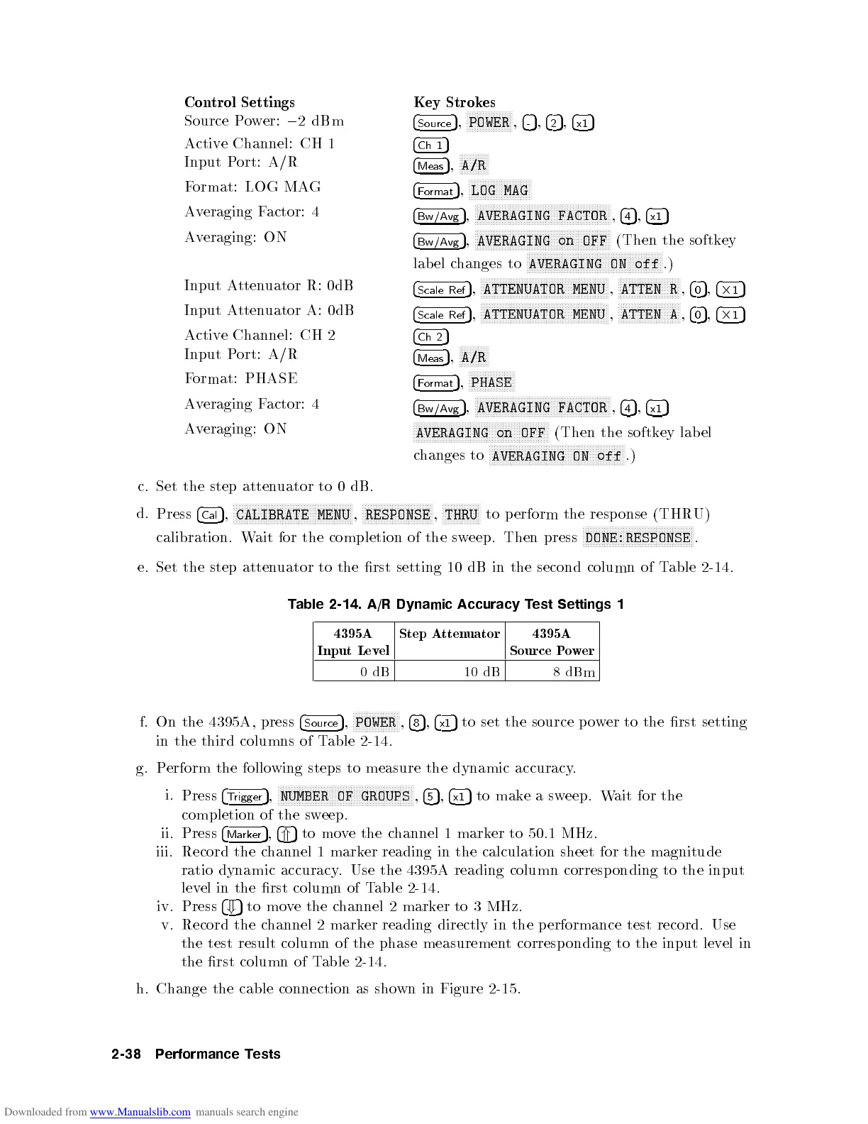
T
able 2-14.
A/R Dynamic
Accuracy
T
est
Settings
1
4395A
Input
Lev
el
Step
A
tten
uator
4395A
Source
P
o
w
er
0
dB
10
dB
8
dBm
f.
On
the
4395A
,
press
4
Source
5
,
NN
NN
NN
N
N
N
N
N
N
N
N
N
N
N
POWER
,
4
8
5
,
4
x1
5
to
set
the
source
p
o
w
er
to
the
rst setting
in
the
third
columns
of
T
able
2-14.
g.
Perform
the
follo
wing
steps
to
measure
the
dynamic
accuracy
.
i.
Press
4
Trigger
5
,
NNNNNNNNNNNNN
NNNNNNNNNNNNNNNNNNNNNNNNN
NNNNNNNNNNNN
NUMBER OF GROUPS
,
4
5
5
,
4
x1
5
to mak
ea sw
eep. W
ait for the
completion of the sw
eep.
ii.
Press
4
Marker
5
,
4
*
5
to mo
ve the c
hannel 1 mark
er to 50.1 MHz.
iii. Record the c
hannel 1 mark
er reading in the calculation sheet for the magnitude
ratio dynamic accuracy
. Use the
4395A reading column corresponding to the input
level in the
rst column of T
able 2-14.
iv. Press
4
+
5
to movethe channel 2 marker to 3 MHz.
v. Record the channel 2 marker reading directly in the performance test record. Use
the test result column of the phase measurement corresp onding to the input level in
the rst column of Table 2-14.
h. Change the cable connection as shown in Figure 2-15 .
2-38 Performance Tests
 Loading...


