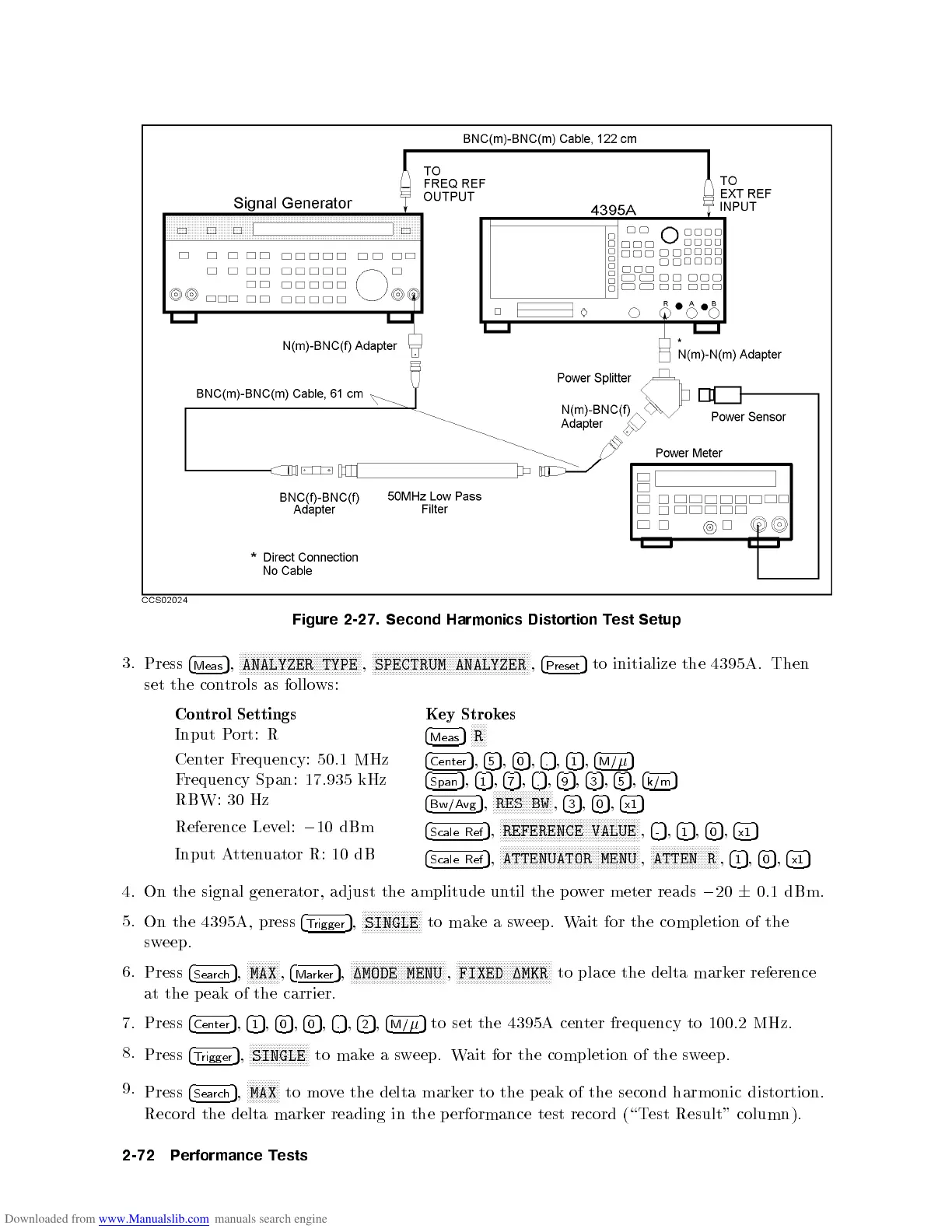
Figure
2-27.
Second
Harmonics
Distortion
Test
Setup
3.
Press
4
Meas
5
,
N
N
N
N
N
N
N
N
N
N
N
N
N
N
N
N
N
N
N
N
NN
N
N
N
N
N
N
N
N
N
N
N
N
N
N
N
N
N
N
N
ANALYZER
TYPE
,
N
N
N
N
N
N
N
N
N
N
N
N
N
N
N
N
N
N
N
N
NN
N
N
N
N
N
N
N
N
N
N
N
N
N
N
N
N
N
N
N
N
N
N
N
NN
N
N
N
N
N
N
SPECTRUM
ANALYZER
,
4
Preset
5
to
initialize
the
4395A
.
Then
set
the
con
trols
as
follo
ws:
Con
trol
Settings
Key
Strok
es
Input
P
ort:
R
4
Meas
5
N
N
N
N
N
R
Cen
ter
F
requency:
50.1
MHz
4
Center
5
,
4
5
5
,
4
0
5
,
4
.
5
,
4
1
5
,
4
M/
5
Frequency
Span: 17.935
kHz
4
Span
5
,
4
1
5
,
4
7
5
,
4
.
5
,
4
9
5
,
4
3
5
,
4
5
5
,
4
k/m
5
RBW:
30
Hz
4
Bw/Avg
5
,
NN
NN
N
N
N
N
N
N
N
N
N
N
N
N
N
N
N
N
RES
BW
,
4
3
5
,
4
0
5
,
4
x1
5
Reference
Lev
el:
0
10 dBm
4
Scale
Ref
5
,
N
N
N
N
N
N
N
N
N
N
N
NN
NN
NN
NN
NN
NN
NN
N
N
N
N
N
N
N
N
N
N
N
NN
NN
NN
NN
NN
N
REFERENCE
VALUE
,
4
-
5
,
4
1
5
,
4
0
5
,
4
x1
5
Input A
ttenuator R: 10 dB
4
Scale Ref
5
,
NNNN
NNNNNNNNNNNNNNNNNNNNNNNNN
NNNNNNNNNNNNNNNNNN
ATTENUATOR MENU
,
NNNN
NNNNNNNNNNNNNNNNNNN
ATTEN R
,
4
1
5
,
4
0
5
,
4
x1
5
4. On the signal generator, adjust the amplitude un
til the po
wer meter reads
0
20
6
0.1 dBm.
5.
On the 4395A, press
4
T
rigger
5
,
NNNNNNNNN
NNNNNNNNNNN
SINGLE
to mak
easw
eep. W
ait for
the completion of the
sweep.
6.
Press
4
Search
5
,
NNNNNNNNNNN
MAX
,
4
Marker
5
,
NNNNNNNNNNNNNNNNNNNNN
NNNNNNNNNNN
1MODE MENU
,
NNNNNNNNNNNNNNNNNNNNN
NNNNNNNNNNN
FIXED 1MKR
to place the delta mark
er reference
at the p eak of the carrier.
7. Press
4
Center
5
,
4
1
5
,
4
0
5
,
4
0
5
,
4
.
5
,
4
2
5
,
4
M/
5
to set the 4395A center frequency to 100.2 MHz.
8.
Press
4
Trigger
5
,
NNNNNNNNNNNNNNNNNNNN
SINGLE
to makeasweep. Wait for the completion of the sweep.
9.
Press
4
Search
5
,
NNNNNNNNNNN
MAX
to move the delta marker to the p eak of the second harmonic distortion.
Record the delta marker reading in the performance test record (\Test Result" column).
2-72 Performance Tests
 Loading...


