If
the v
oltmeter reading
is within
the limits,
the A50
+5 VD
p
o
w
er
supply
is
v
eried.
Turn
the analyzer
p
o
w
er
o
and
reconnect
the
cable
to
the
A50J3. Then
contin
ue with
the
next
Disc
onne
ct
Cables
on the
A1 CPU
section.
3.
Disconnect
Cables
on
the
A1
CPU
a.
Turn
the analyzer
p
o
w
er
o.
b.
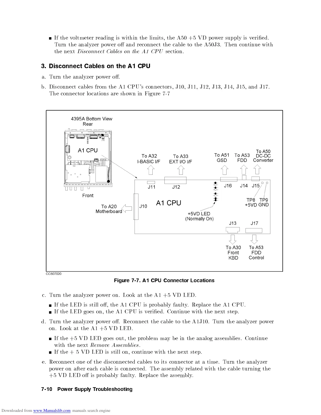
Disconnect
cables
from
the
A1
CPU's
connectors,
J10,
J11,
J12,
J13,
J14,
J15, and
J17.
The
connector
lo
cations
are sho
wn in
Figure 7-7
Figure
7-7. A1
CPU
Connector
Locations
c. T
urn the analyzer po
wer on. Lo ok at the A1 +5 VD LED.
If the LED is still o, the A1 CPU is probably faulty
. Replace the A1 CPU.
If the LED go es on, the A1 CPU is v
eried. Con
tinue with the next step.
d. T
urn the
analyzer p o
wer o. Reconnect the cable to the A1J10. T
urn the analyzer p o
wer
on. Lo ok at the A1 +5 VD LED.
If the +5 VD LED go es out, the problem may b e in the analog assemblies. Continue
with the next
Remove Assemblies
.
If the + 5 VD LED is still on, continue with the next step.
e. Reconnect one of the disconnected cables to its connector at a time. Turn the analyzer
power on after each cable is connected. The assembly related with the cable turning the
+5 VD LED o is probably faulty. Replace the assembly.
7-10 Power Supply Troubleshooting
 Loading...


