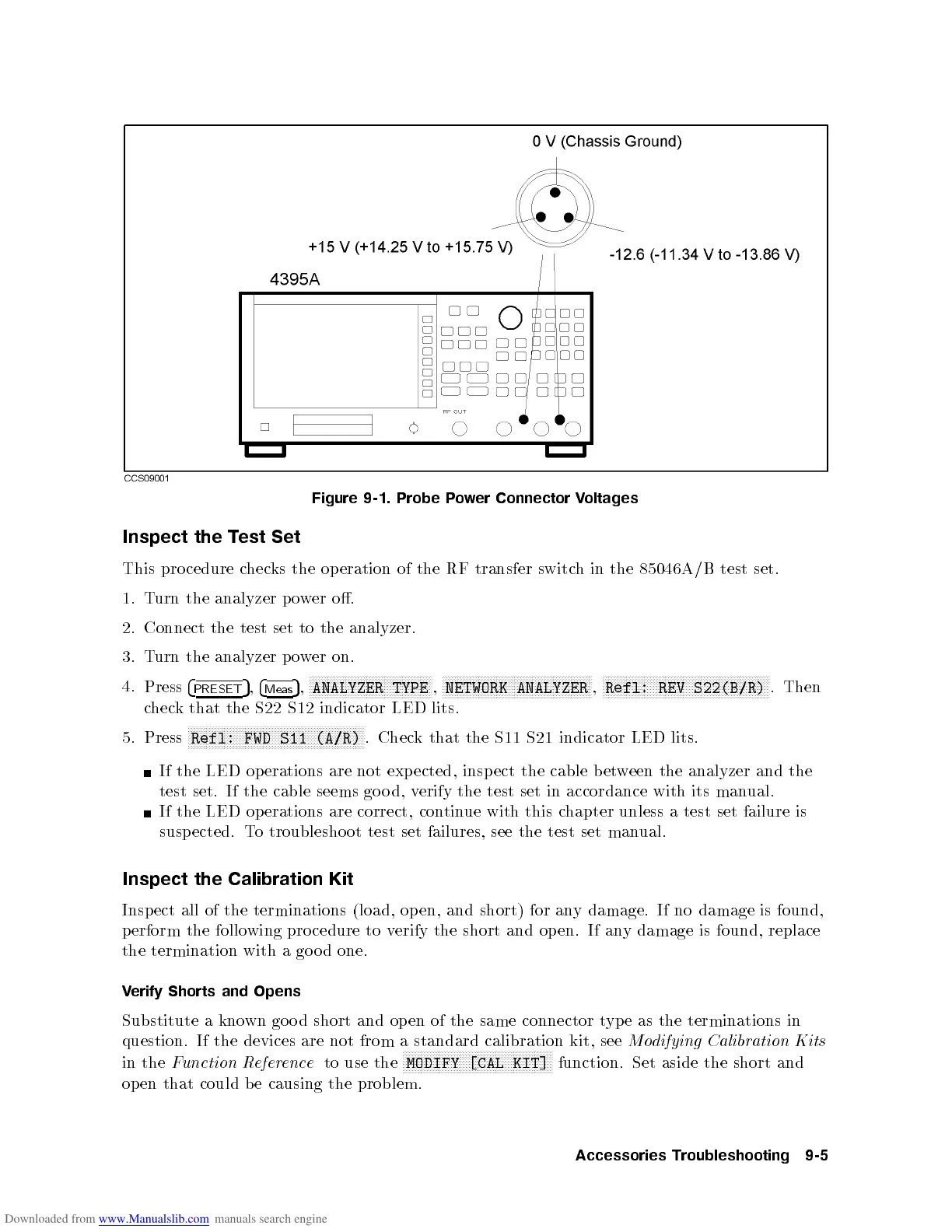
Figure
9-1.
Probe
P
o
w
er
Connector
V
oltages
Inspect
the
T
est
Set
This
pro
cedure
c
hec
ks
the
op
eration
of
the
RF
transfer
switc
h
in
the 85046A/B
test
set.
1.
T
urn
the
analyzer
p
o
w
er
o.
2.
Connect
the
test
set
to
the
analyzer.
3.
T
urn
the
analyzer
p
ow
er
on.
4.
Press
4
PRESET
5
,
4
Meas
5
,
N
NN
N
N
N
N
N
N
N
N
N
N
N
N
N
N
N
N
N
N
N
N
N
NN
NN
N
N
N
N
N
N
N
N
N
N
N
N
N
ANALYZER
TYPE
,
N
NN
N
N
N
N
N
N
N
N
N
N
N
N
N
N
N
N
N
N
N
N
N
NN
NN
N
N
N
N
N
N
N
N
N
N
N
N
N
N
N
N
N
N
N
N
N
N
NETWORK
ANALYZER
,
N
NN
N
N
N
N
N
N
N
N
N
N
N
N
N
N
N
N
N
N
N
N
N
NN
NN
N
N
N
N
N
N
N
N
N
N
N
N
N
N
N
N
N
N
N
N
N
NN
NN
N
N
N
Refl:
REV
S22(B/R)
.
Then
c
hec
k
that
the
S22
S12
indicator
LED
lits.
5.
Press
N
N
NN
NN
NN
NN
N
N
N
N
N
N
N
N
N
N
N
N
N
N
N
N
N
NN
NN
NN
NN
N
N
N
N
N
N
N
N
N
N
N
N
N
N
N
N
N
NN
NN
NN
N
Refl:
FWD
S11
(A/R)
.
Chec
k
that
the
S11
S21
indicator
LED
lits.
If
the
LED
op
erations
are
not
exp
ected,
insp
ect
the
cable b
etw
een the
analyzer
and
the
test set.
If
the
cable
seems
go
o
d,
v
erify
the
test
set
in
accordance
with
its
man
ual.
If
the LED
operations
are correct,
contin
ue with
this
c
hapter
unless
a
test
set
failure
is
susp
ected.
T
o
troublesho
ot test
set
failures,
see
the
test
set
man
ual.
Inspect
the Calibration Kit
Inspect all of the terminations (load, op en, and short) for an
y
damage. If no damage is found,
perform the follo
wing pro cedure to v
erify the short and op en. If an
y damage is found, replace
the termination with a go o d one.
Verify Shorts and Opens
Substitute a known go o d short and op en of the same connector type as the terminations in
question. If the devices are not from a standard calibration kit, see
Modifying Calibration Kits
in the
Function Reference
to use the
NNNNNNNNNNNNNNNNNNNNNNNNNNNNNNNNNNNNNNNNNNNNNNNNNN
MODIFY [CAL KIT]
function. Set aside the short and
open that could b e causing the problem.
Accessories Troubleshooting 9-5
 Loading...


