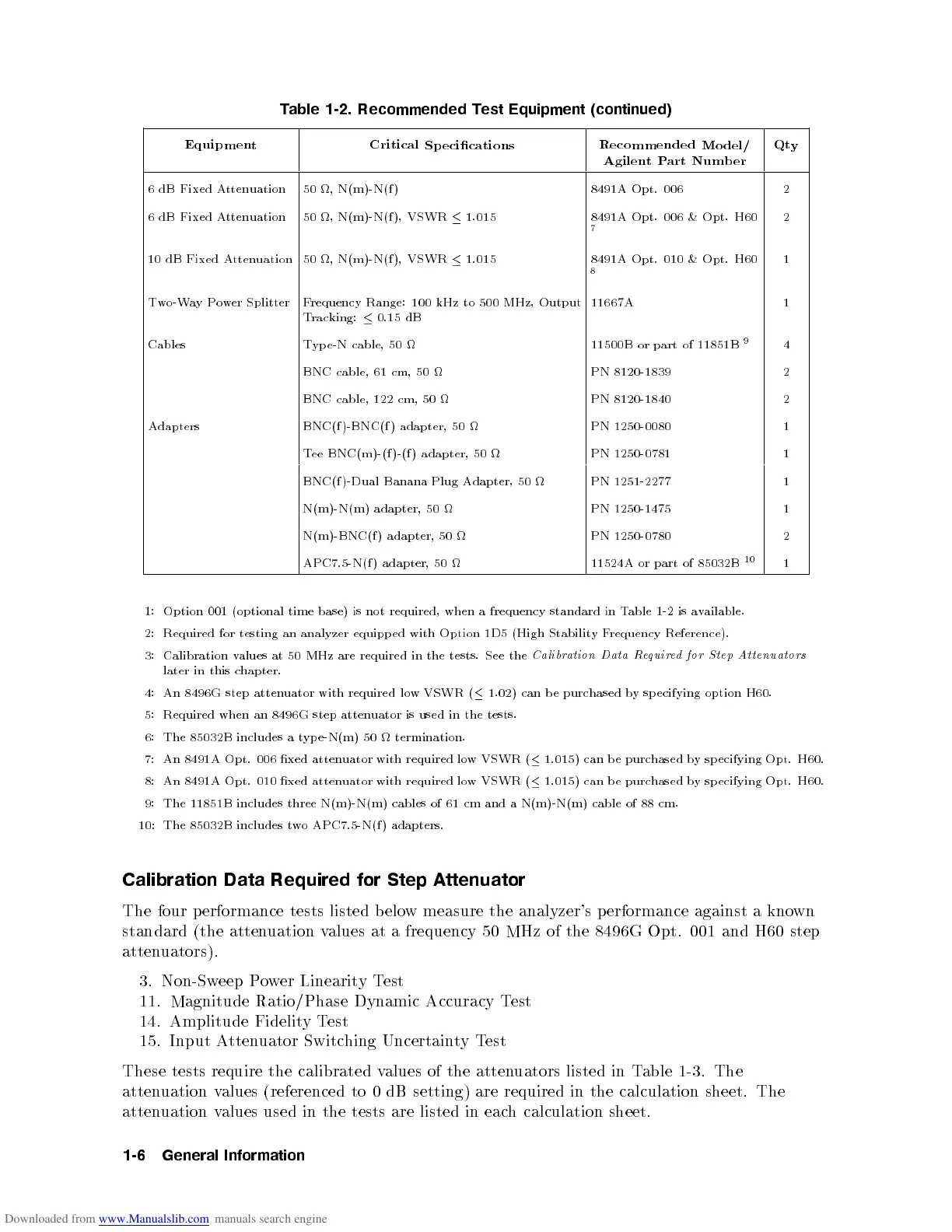
Table
1-2. Recommended
Test
Equipment (continued)
Equipmen
t
Critical
Sp ecications
Recommended
Model/
Agilen
t
P
art
Num
b
er
Qt
y
6
dB
Fixed
A
tten
uation
50
,
N(m)-N(f
)
8491A
Opt.
006
2
6
dB
Fixed
A
tten
uation
50
,
N(m)-N(f
),
VSWR
1.015
8491A
Opt.
006
&
Opt.
H60
7
2
10
dB
Fixed
A
tten
uation
50
,
N(m)-N(f
),
VSWR
1.015
8491A
Opt.
010
&
Opt.
H60
8
1
Two-W
ay
Po
w
er
Splitter
Frequency
Range: 100
kHz to
500
MHz,
Output
T
rac
king:
0.15
dB
11667A 1
Cables T
yp
e-N
cable,
50
11500B
or
part
of
11851B
9
4
BNC cable,
61 cm,
50
PN 8120-1839 2
BNC
cable,
122
cm,
50
PN
8120-1840
2
Adapters BNC(f
)-BNC(f
)
adapter,
50
PN
1250-0080
1
T
ee
BNC(m)-(f
)-(f
)
adapter,
50
PN
1250-0781
1
BNC(f
)-Dual
Banana
Plug
Adapter,
50
PN
1251-2277
1
N(m)-N(m)
adapter,
50
PN
1250-1475
1
N(m)-BNC(f
)
adapter,
50
PN
1250-0780
2
APC7.5-N(f
)
adapter,
50
11524A
or
part
of
85032B
10
1
1:
Option
001
(optional
time
base)
is
not
required,
when
a
frequency
standard
in
Table
1-2
is
a
v
ailable.
2:
Required
for
testing
an
analyzer
equipp
ed
with
Option
1D5
(High
Stabilit
y
F
requency
Reference).
3:
Calibration
v
alues
at
50
MHz
are
required
in
the
tests.
See
the
Calibr
ation
Data
Re
quir
e
d
for
Step
A
ttenuators
later
in
this
c
hapter.
4:
An
8496G
step
atten
uator
with
required
lo
w
VSWR
(
1.02)
can
b
e
purchased
by
sp
ecifying
option
H60.
5:
Required
when
an
8496G
step
atten
uator
is
used
in
the
tests.
6:
The
85032B
includes
a
t
yp
e-N(m)
50
termination.
7:
An
8491A
Opt.
006
xed
atten
uator
with
required
lo
w
VSWR
(
1.015)
can b
e purc
hased b
y
sp
ecifying
Opt.
H60.
8:
An
8491A
Opt.
010
xed
atten
uator
with
required
lo
w
VSWR
(
1.015) can
be
purchased
b
y
sp
ecifying
Opt.
H60.
9:
The
11851B
includes
three
N(m)-N(m)
cables
of
61
cm
and a
N(m)-N(m) cable
of 88
cm.
10:
The
85032B
includes
t
wo
APC7.5-N(f )
adapters.
Calibration Data Required for Step A
ttenuator
The four performance tests listed b elo
w measure the analyzer's performance against a kno
wn
standard (the atten
uation v
alues at a frequency 50 MHz
of the 8496G Opt. 001 and H60 step
attenuators).
3. Non-Sw
eep P
ower Linearit
yT
est
11. Magnitude Ratio/Phase Dynamic Accuracy Test
14. Amplitude FidelityTest
15. Input Attenuator Switching UncertaintyTest
These tests require the calibrated values of the attenuators listed in Table 1-3. The
attenuation values (referenced to 0 dB setting) are required in the calculation sheet. The
attenuation values used in the tests are listed in each calculation sheet.
1-6 General Information
 Loading...


