11.
MAGNITUDE
RATIO/PHASE
D
YNAMIC
A
CCURA
CY
TEST
(NA)
Description
Dynamic accuracy
is a
measure of
how
well
a
receiv
er
measures
the
magnitude
and
phase
comp
onen
ts
of
a
signal
as
that
signal
v
aries
in
amplitude
o
v
er
asp
ecied dynamic
range.
T
o
measure
the
dynamic
accuracy
,
this
test
applies
a
xed lev
el signal
of
0
20 dBm
to
the
4395A
R
input (reference
input). A
tthe
same time,
it
applies
a
signal
that
v
aries
from
0
10
dBm
(full
scale
input
lev
el)
to
0
110
dBm
to
one
of
the
4395A
's
A
or
B inputs
(test input).
It
then
measures
the
magnitude
ratio
from
0
10
dB
to
0
100 dB
and the
phase of
the
signals.
The
signal
amplitude
at
the
test
input
is
v
aried
by
inserting kno
wn atten
uation
v
alues.
The
measured
magnitude ratio
values
are then
compared
to
the
inserted
atten
uation's
calibrated
v
alues.
The
phase
dynamic
accuracy
is
measured
at
3
MHz
(where
the
phase
error
con
tribution
b
y
the
individual
atten
uator
segmen
ts
is
small
when
compared
to
the
test
limits).
In
this
test,
a
step
attenuator
with its
VSWR
1.02
and
t
w
o
6
dB
xed
atten
uators
with
a
VSWR
1.015
are
used.
Using
these
atten
uators
reduces
the
measurement
uncertainties
caused b
y
mismatc
h
error.
When
they
are
used,
the
measuremen
t
uncertain
ties
listed
in
the
p
erformance
test
record are
valid.
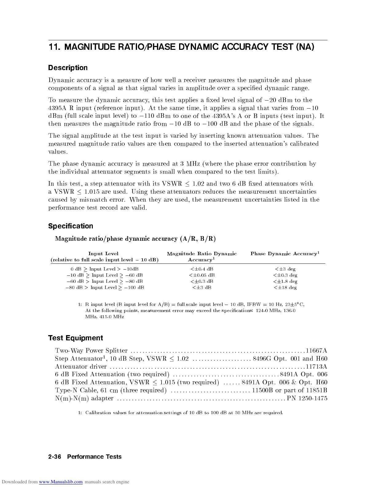
Specification
Magnitude
ratio/phase
dynamic accuracy
(A/R,
B/R)
Input
Lev
el
(relativ
e
to
full
scale
input
lev
el
0
10
dB)
Magnitude
Ratio
Dynamic
Accuracy
1
Phase
Dynamic
Accuracy
1
0
dB
Input Lev
el
>
0
10dB
<
6
0.4
dB
<
6
3
deg
0
10
dB
Input
Lev
el
0
60
dB
<
6
0.05
dB
<
6
0.3
deg
0
60
dB
>
Input Lev
el
0
80
dB
<
6
0.3
dB
<
6
1.8
deg
0
80 dB
>
Input
Level
0
100
dB
<
6
3
dB
<
6
18
deg
1: R
input lev
el
(B
input
lev
el
for
A/B)
=
full
scale
input
lev
el
0
10
dB,
IFBW
=
10
Hz, 23
6
5
C,
A
tthe
following
poin
ts, measuremen
t
error
ma
y
exceed
the
sp
ecications:
124.0
MHz,
136.0
MHz,
415.0
MHz
Test Equipment
Two-WayP
ower Splitter
::::::::: ::::: ::::: ::
:::::::: ::::: ::::: ::::: ::
:::::::: :::::
11667A
Step A
ttenuator
1
, 10 dB Step, VSWR
1.02
::::::: ::::: :
:::::::
8496G Opt. 001 and H60
Attenuator driv
er
::::
:::::: ::::: :::: ::::: :::::
:::::::::: ::::: ::::: :::::
:::::::::: ::
11713A
6 dB Fixed A
ttenuation (t
w
o required)
::::::: ::::: ::::: :::: ::
:::::::: :::::
8491A Opt. 006
6 dB Fixed A
ttenuation, VSWR
1.015 (t
wo required)
::::::
8491A Opt. 006 &
Opt. H60
Type-N Cable, 61 cm (three required)
:::::
:::::: ::::: ::::: ::::: :
11500B or part
of 11851B
N(m)-N(m) adapter
::::::: ::::: ::::: ::::: ::::: ::::: ::::: ::::: :::::::::: :::::
PN 1250-1475
1: Calibration values for attenuation settings of 10 dB to 100 dB at 50 MHz are required.
2-36 Performance Tests
 Loading...


