6.
Press
4
Scale Ref
5
,
NN
NN
N
N
N
N
N
N
N
N
N
N
N
N
N
NN
NN
NN
NN
NN
NN
N
N
N
N
N
N
N
N
N
N
N
N
N
NN
NN
N
REFERENCE
VALUE
,
4
-
5
,
4
1
5
,
4
0
5
,
4
x1
5
,
4
Scale Ref
5
,
NN
NN
N
N
N
N
N
N
N
N
N
N
N
N
N
NN
NN
NN
NN
NN
NN
N
N
N
N
N
N
N
N
N
N
N
N
N
NN
NN
N
ATTENUATOR
MENU
,
N
NN
N
N
N
N
N
N
N
N
N
N
N
NN
NN
NN
NN
N
ATTEN
R
,
4
1
5
,
4
0
5
,
4
x1
5
,
to
set
the
4395A
con
trols
to the
reference setting
for the
test.
7.
Set the
step atten
uator to
10
dB.
8.
P
erform
the
follo
wing
steps
to
measure
the amplitude
delity
.
a.
On
the
4395A
,
press
4
Sea
rch
5
,
N
NN
NN
N
N
N
N
N
N
MAX
to
mo
v
e
the
mark
er
to
the
p
eak
of
the
carrier.
b.
On the
signal generator,
adjust
the
amplitude
un
til
the
4395A
mark
er
reads
0
20
dB
6
0.1
dB.
c.
On
the
4395A
,press
4
T
rigger
5
,
N
N
N
N
N
N
N
N
N
N
NN
NN
NN
NN
N
N
SINGLE
to
mak
e
asw
eep. W
ait for
the completion
of
the
sw
eep.
d.
Press
4
Sea
rch
5
,
N
N
N
N
NN
NN
NN
N
MAX
,
4
Ma
rk
er
5
,
N
N
N
N
NN
NN
NN
NN
N
N
N
N
N
N
N
N
N
N
N
N
N
N
N
N
N
NN
N
1MODE MENU
,
N
N
N
N
NN
NN
NN
NN
N
N
N
N
N
N
N
N
N
N
N
N
N
N
N
N
N
NN
N
FIXED 1MKR
to place
the delta
reference
mark
er
on
the
p
eak
of
the
carrier
(reference
lev
el of
the amplitude
delity).
e.
Set
the step
attenuator
to the
rst
setting
20
dB
in
the
second
column
of
T
able
2-19
.
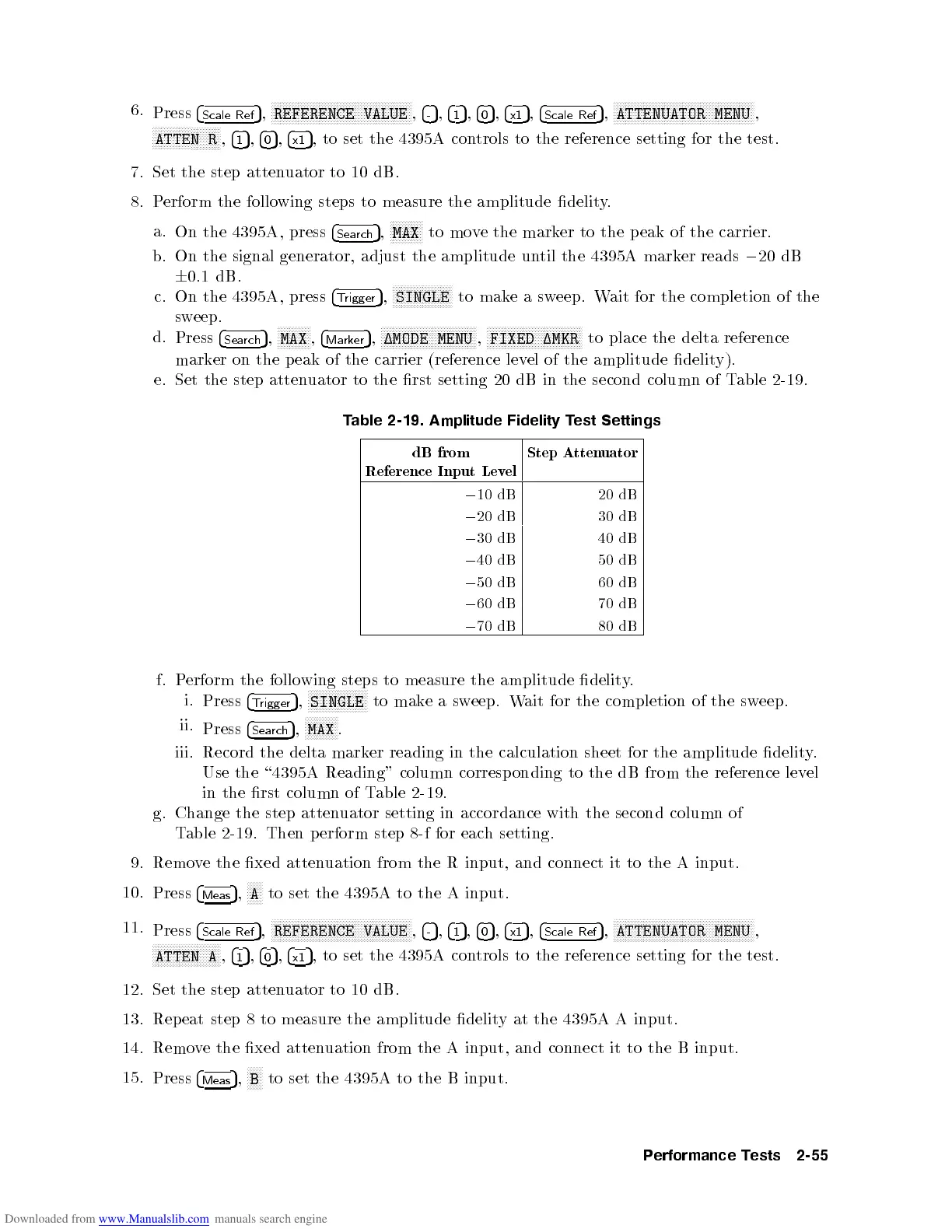
T
able
2-19.
Amplitude
Fidelity
T
est
Settings
dB
from
Reference
Input
Lev
el
Step
A
tten
uator
0
10 dB
20
dB
0
20
dB
30
dB
0
30
dB
40
dB
0
40 dB
50
dB
0
50
dB
60
dB
0
60
dB
70
dB
0
70
dB
80
dB
f.
P
erform the
following
steps
to
measure
the
amplitude
delit
y
.
i.
Press
4
T
rigger
5
,
N
N
N
N
N
N
N
N
N
N
N
N
N
N
N
N
N
N
N
N
SINGLE
to
mak
e
a
sw
eep.
W
ait for
the completion
of
the
sw
eep.
ii.
Press
4
Sea
rch
5
,
N
N
N
N
N
N
N
N
N
N
N
MAX
.
iii.
Record
the
delta
mark
er
reading
in
the
calculation
sheet
for
the amplitude
delity
.
Use the
\
4395A
Reading"
column
corresp
onding
to
the
dB
from
the
reference
lev
el
in
the rst
column of
Table
2-19.
g.
Change
the
step
atten
uator
setting in
accordance with
the second
column of
Table
2-19
.
Then
p
erform
step
8-f
for
eac
h
setting.
9. Remo
ve the xed atten
uation from the R input, and connect
it to the A input.
10.
Press
4
Meas
5
,
N
NNNN
A
to
set the 4395A to the A input.
11.
Press
4
Scale Ref
5
,
NNNNNNNNNNN
NNNNNNNNNNNNNNNNNNNNNNNNN
NNNNNNNNNNN
REFERENCE VALUE
,
4
-
5
,
4
1
5
,
4
0
5
,
4
x1
5
,
4
Scale Ref
5
,
NNNNNNNNNNN
NNNNNNNNNNNNNNNNNNNNNNNNN
NNNNNNNNNNN
ATTENUATOR MENU
,
NNNNNNNNNNNNNNNNNNNNNNN
ATTEN A
,
4
1
5
,
4
0
5
,
4
x1
5
,
to set the 4395A con
trols to the reference setting for the test.
12. Set the step atten
uator to 10 dB.
13. Repeat step 8 to measure the amplitude delity at the 4395A A input.
14. Remove the xed attenuation from the A input, and connect it to the B input.
15.
Press
4
Meas
5
,
NNNNN
B
to set the 4395A to the B input.
Performance Tests 2-55
 Loading...


