101
6
Component Location and Circuit Diagrams
This chapter contains component location diagrams, schematics, and other drawings useful for maintenance of the power
supply. Included in this section are:
a.
Component location illustrations (Figures 6-1 through 6-9), showing the physical location and reference designators of
almost all electrical parts. (Components located on the rear panel are easily identified.)
b.
Notes (Table 6-1) that apply to all schematic diagrams.
c.
Schematic diagrams (Figures 6-10 through 6-13).
AC line voltage is present on the A1 Main Board Assembly whenever the power cord is connected to an ac
power source.
Table 6-1. Schematic Diagram Notes
1.
.
denotes front-panel marking.
2.
denotes rear-panel marking.
3. Complete reference designator consists of component reference designator prefixed with assembly number (e.g.:
A2R14).
4. Resistor values are in ohms. Unless otherwise noted, resistors are either 1/4W, 5% or 1/8W, 1%. Parts list provides
power rating and tolerance for all resistors.
5. Unless otherwise noted, capacitor values are in microfarads.
6. Square p.c. pads indicate one of the following:
a. pin 1 of an integrated circuit.
b. the cathode of a diode or emitter of a transistor.
c. the positive end of a polarized capacitor.
7. Schematic components marked with an asterisk (*) indicate that different values are used in each model. Refer to the
parts list for the applicable values.
8. Schematic components marked with a dagger (
† ) are listed under chassis, electrical in the parts list.
9. This capacitor is only used on 6030A and 6035A units. C6 is mounted on the chassis on 6030A units. C3 is mounted
on the A9 board on 6035A units.
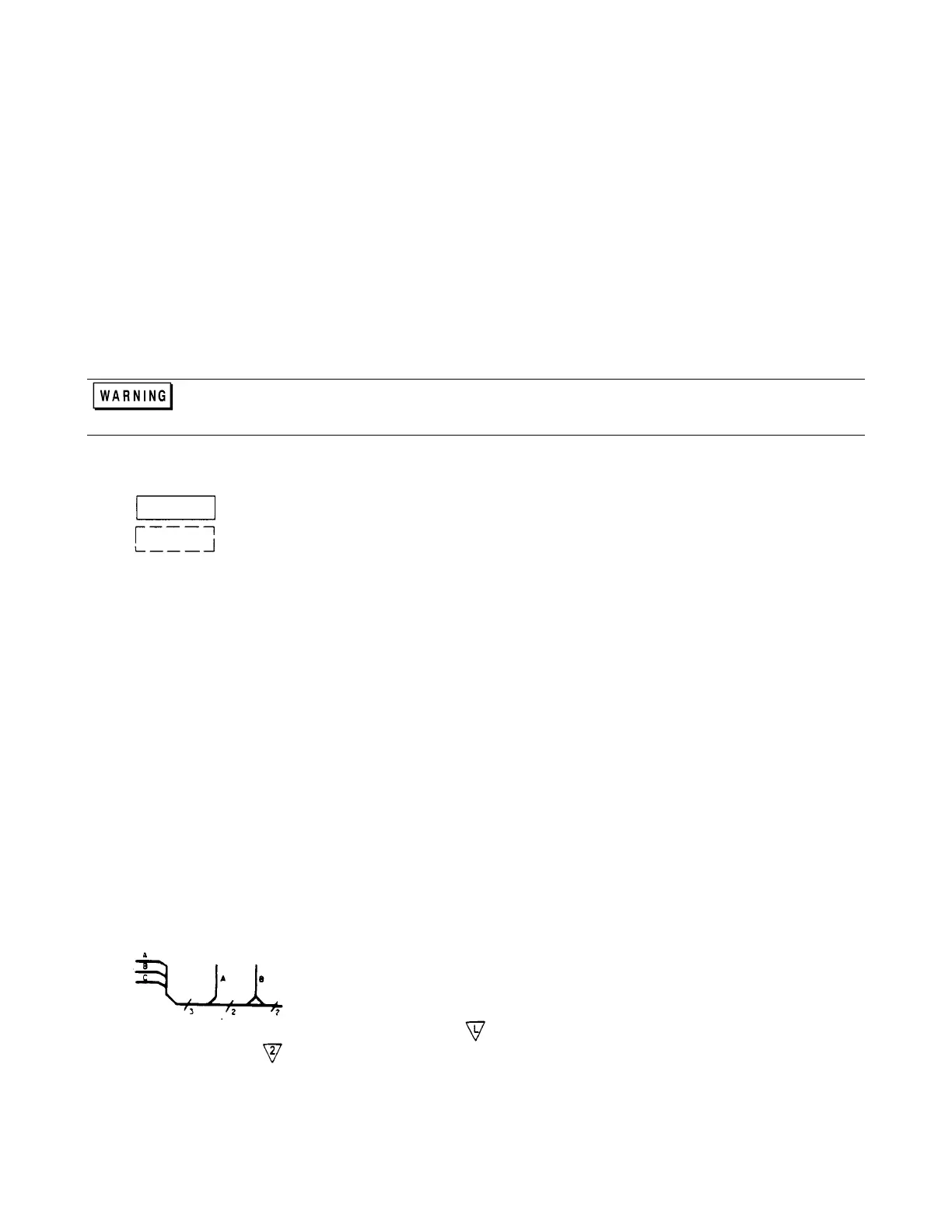
10.
indicates multiple paths represented by only one line. Reference designators with pin
numbers indicate destination, or signal names identify individual paths. Numbers
indicate number of paths represented by the line.
11.
Inter-board commons have letter identifications (e.g.:
); commons existing on a single assembly have number
identifications (e.g.:
).
Artisan Technology Group - Quality Instrumentation ... Guaranteed | (888) 88-SOURCE | www.artisantg.com