22
You may substitute:
3.5Ω 1000W load resistor (6030A)
0.069Ω 1000W load resistor (6031A)
0.4Ω 1000W load resistor (6032A)
40Ω 1000W load resistor (6035A)
in these tests:
CV Load Effect (Load Regulation)
CV PARD (Ripple and Noise)
CC Source Effect (Line Regulation)
CC PARD (Ripple and Noise)
The substitution of the load resistor requires adding a load switch and making minor changes to the procedures. The load
transient recovery time test procedure is not amenable to modification for use with load resistors.
An electronic load is considerably easier to use than a load resistor. It eliminates the need for connecting resistors or
rheostats in parallel to handle the power, it is much more stable than a carbon-pile load, and it makes easy work of switching
between load conditions as is required for the load regulation and load transient-response tests.
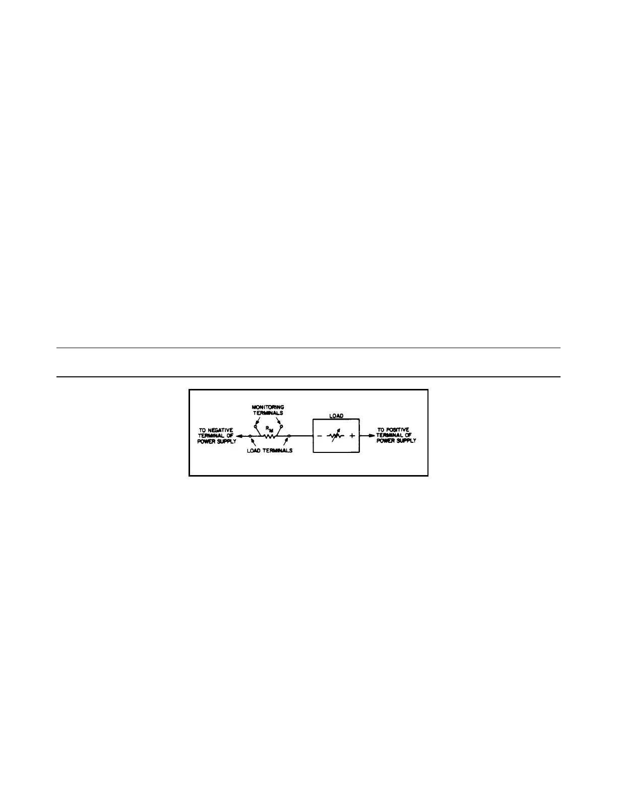
Current-Monitoring Resistor. To eliminate output current measurement error caused by voltage drops in the leads and
connections, connect the current-monitoring resistor between -OUT and the load as a four-terminal device. Figure 2-4
shows correct connections. Connect the current-monitoring test leads inside the load-lead connections directly at the
monitoring resistor element.
Note: A current-monitoring resistor with 1% accuracy is suitable for all tests except current programming
accuracy and current readback accuracy. For these tests, use the shunt listed in Table 2-1.
Figure 2-4. Current-Monitoring Resistor Setup
GPIB Controller. Most performance tests can be performed using only front-panel controls. However, a GPIB controller is
required to perform the voltage and current programming accuracy tests and the voltage and current readback accuracy tests.
Constant Voltage (CV) Tests
CV Setup. If more than one meter or a meter and an oscilloscope are used, connect each to the + S and - S terminals by a
separate pair of leads to avoid mutual coupling effects. Connect only to + S and -S because the unit regulates the output
voltage between + S and - S, not between + OUT and -OUT. Use coaxial cable or shielded 2-wire cable to avoid pickup on
test leads. For all CV tests set the output current at full output to assure CV operation.
Voltage Programming And Readback Accuracy. This procedure verifies that the voltage programming and readback
functions are within specifications. A GPIB controller must be used for this test.
a. Connect digital voltmeter between + S and - S.
b. Turn on ac power to the power supply.
c. Send string:
"VSET 0.5; ISET 17" (6030A)
Artisan Technology Group - Quality Instrumentation ... Guaranteed | (888) 88-SOURCE | www.artisantg.com