Verification 13
Programming
You can program the supply from the front panel keyboard or from a GPIB controller (for models 664xA and 665xA) when
performing the tests. The test procedures are written assuming that you know how to program the supply either; remotely
from a GPIB controller (for 664xA and 665xA models), or locally using the control keys and indicators on the supply’s front
panel. For models 654xA and 655xA you must use the front panel. Complete instructions on remote and local programming
are given in the Operating Manual.
Constant Voltage (CV) Tests
CV Setup
If more than one meter or if a meter and an oscilloscope are used, connect each to the terminals by a separate pair of leads to
avoid mutual coupling effects. For constant voltage DC tests, connect only to +S and -S, since the unit regulates the output
voltage that appears between +S and -S, and not between the (+) and (-) output terminals. Use coaxial cable or shielded
two-wire cable to avoid noise pickup on the test leads.
Voltage Programming and Readback Accuracy
This test verifies that the voltage programming, GPIB readback (on 664xA and 665xA models), and front panel display
functions are within specifications. Note that the values read back over the GPIB should be identical to those displayed on
the front panel.
a. Turn off the supply and connect a digital voltmeter between the +S and the -S terminals as shown in Figure 2-1.
b. Turn on the supply and program the supply to zero volts and the maximum programmable current (see Table 2-3) with
the load off.
c. Record the output voltage readings on the digital voltmeter (DVM) and the front panel display. The readings should be
within the limits specified in the performance test record form for the appropriate model under CV PROGRAMMING
@ 0 VOLTS. Also, note that the CV annunciator is on. The output current reading should be approximately zero.
d. Program the output voltage to full-scale (see Table 2-3).
e. Record the output voltage readings on the DVM and the front panel display. The readings should be within the limits
specified in the performance test record form for the appropriate model under CV PROGRAMMING @ FULL
SCALE.
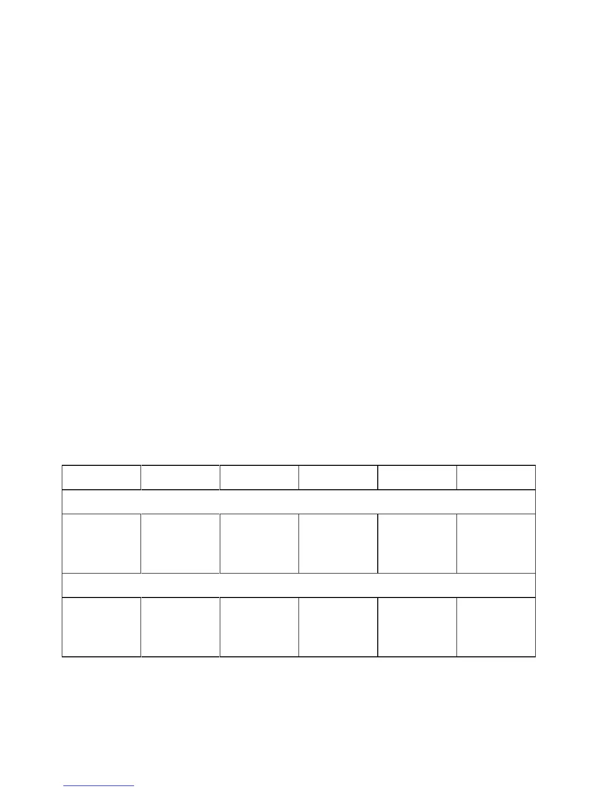
Table 2-3. Voltage and Current Values
Agilent Model Full-Scale
Voltage
Max. Prog.
Voltage
Full-Scale
Current
Max. Prog.
Current
Max. Prog.
Overvoltage
200 Watt Supplies
6541A, 6641A 8 V 8.190 V 20 A 20.475 A 8.8 V
6542A, 6642A 20 V 20.475 V 10 A 10.237 A 22 V
6543A, 6643A 35 V 35.831 V 6 A 6.142 A 38.5 V
6544A, 6644A 60 V 61.425 V 3.5 A 3.583 A 66.0 V
6545A, 6645A 120 V 122.85 V 1.5 A 1.535 A 132 V
500 Watt Supplies
6551A, 6651A 8 V 8.190 V 50 A 51.188 A 8.8 V
6552A, 6652A 20 V 20.475 V 25 A 25.594 A 22 V
6553A, 6653A 35 V 35.831 V 15 A 15.536 A 38.5 V
6554A, 6654A 60 V 61.425 V 9 A 9.214 A 66.0 V
6555A, 6655A 120 V 122.85 V 4 A 4.095 A 132 V
 Loading...


