Introduction
7
1
Introduction
Scope
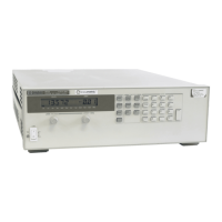
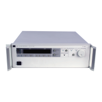
This manual contains information for troubleshooting and repairing four generic models of Agilent power supplies. The
different power supply models described in this manual are listed in Table 1-1.
Note The information provided in this manual applies to all Agilent models listed in Table 1-1. Where
differences exist among any of the models, these differences are explained in text.
For installation, operation, programming, and calibration procedures, refer to the appropriate Operating Manual as listed in
Chapter 2, Table 2-1. For information in determining the performance level of the power supply, either before or after
repair, refer to Chapter 2, Verification. The functional circuit operation of the various Agilent models is described in
Chapter 4. Replaceable parts lists and circuit diagrams are included in Chapters 5 and 6, respectively.
Table 1-1. Agilent Power Supplies Described In This Manual
Agilent Models 200 Watt Models 500 Watt Models
GPIB Agilent 6641A-6645A Agilent 6651A-6655A
Analog Programmable Agilent 6541A-6545A Agilent 6551A-6555A
Conventions Used In Text
1. Power supply models can be divided into 200 watt and 500 watt models. A "4" in the third position of the model
number indicates a 200 watt supply, while the digit "5" in the third position indicates a 500 watt unit.
2. In addition, power supplies can be divided according to GPIB supplies or Analog Programmable supplies. All GPIB
models have a “6” in the second position of the model number, while Analog Programmable supplies have a “5” in the
second position of the model number. The GPIB models include a GPIB board which permits communications between
the supply and an external computer over the GPIB bus. Analog Programmable supplies use an Isolator Board instead
of the GPIB board, and do not have the ability to communicate with an external computer.
3. When referring in text to either the 200 watt or 500 watt GPIB power supply models, the convention “models 664xA or
665xA,” respectively, is used. When referring to either the 200 watt or 500 watt non- GPIB (or Analog Programmable)
models, the convention “models 654xA or 655xA,” respectively, is used.
4. In this manual all complementary signal names in text are shown with an asterisk (*) after the signal name. Example;
PCLR*. In some schematic diagrams you may see a bar above the signal name, which is identical to the signal name
shown in text with an asterisk.

 Loading...


