Verification 15
Transient Recovery Time
This test measures the time for the output voltage to recover to within the specified value following a 50% change in the
load current.
a. Turn off the supply and connect the output as in Figure 2-1 with the oscilloscope across the +S and the -S terminals.
b. Turn on the supply and program the output voltage to the full-scale value and the current to the maximum
programmable value (see Table 2-3).
c. Set the load to the Constant Current mode and program the load current to 1/2 the power supply full-scale rated current.
d. Set the electronic load’s transient generator frequency to l00 Hz and its duty cycle to 50%.
e. Program the load’s transient current level to the supply’s full-scale current value and turn the transient on.
f. Adjust the oscilloscope for a waveform similar to that in Figure 2-2.
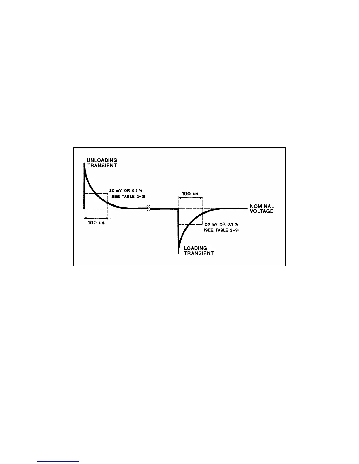
g. The output voltage should return to within 0.1% or 20 mV, whichever is greater, of the nominal value in less than 100
microseconds. Check both loading and unloading transients by triggering on the positive and negative slope.
Figure 2-2. Transient Response Wavetorm
Constant Current (CC) Tests
CC Setup
Follow the general setup instructions in the Measurement Techniques paragraph and the specific instructions given in the
following paragraphs.
Current Programming and Readback Accuracy
This test verifies that the current programming and readback are within specification. The accuracy of the current
monitoring resistor must be 0.04% or better.
a. Turn off the supply and connect the current monitoring resistor across the output and a DVM across the resistor. See
Current Monitoring Resistor.
b. Turn on the supply and program the output voltage to 5 V and the current to zero.
c. Divide the voltage drop (DVM reading) across the current monitoring resistor by its resistance to convert to amps and
record this value (Iout). Also, record the current reading on the front panel display. The readings should be within the
limits specified in the Performance Test Record Form for the appropriate model under CC PRGRAMMING @ 0 AMPS.
d. Program the output voltage to 5 V and the current to full-scale (see Table 2-3).
 Loading...


