16 Verification
e. Divide the voltage drop (DVM reading) across the current monitoring resistor by its resistance to convert to amps and
record this value (Iout). Also, record the current reading that appears on the front panel display. The readings should be
within the limits specified in the performance test record form for the appropriate model under CC PROGRAMMING
@ FULL-SCALE.
Current Sink (CC-) Operation.
This test verifies current sink operation and readback.
a. Turn off the supply and connect the output as shown in Figure 2-1, except connect a DC power supply in place of the
electronic load as indicated.
b. Set the external power supply to 5 V and its current limit to 20% of the full scale current value (see Table 2-3) of the
supply under test. For example, if the full scale current value is 25 A, set the external supply’s current limit to 5 A.
c. Turn on the supply under test and program the output voltage to zero. The current on the UUT display should be
approximately 20% of the full-scale current.
d. Divide the voltage drop across the current monitoring resistor by its resistance to obtain the current sink value in amps
and subtract this from the current reading on the display. The difference between the readings should be within the
limits specified in the Performance Test Record Form for the appropriate model under, CURRENT SINK DISPLAY
AND READBACK.
CC Load and Line Regulation
These tests (CC Load Effect and CC Source Effect given below) are tests of the DC regulation of the power supply’s output
current. To insure that the values read are not the instantaneous measurement of the AC peaks of the output current ripple,
several DC measurements should be made and the average of these reading calculated. An example of how to do this is
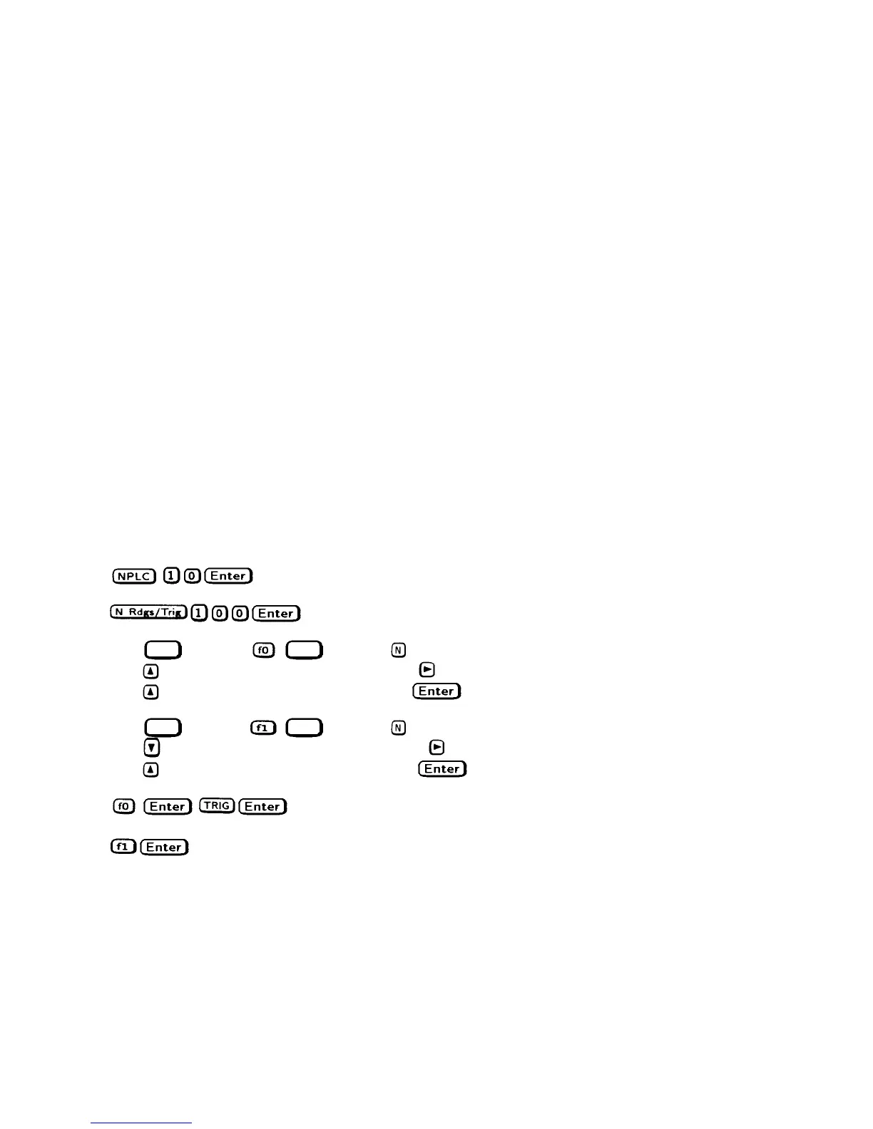
given below using an Agilent 3458A System Voltmeter programmed from the front panel. Set up the voltmeter and execute
the “Average Reading” program as follows:
a. Program 10 power line cycles per sample by pressing
.
b. Program 100 samples per trigger by pressing
.
c. Set up voltmeter to take measurements in the statistical mode as follows:
Press
(shift key)
(shift key)
.
Press
until MATH function is selected, then press .
Press
until STAT function is selected, then press .
d. Set up voltmeter to read the average of the measurements as follows:
Press
(shift key)
(shift key)
.
Press
until RMATH function is selected, then press .
Press
until MEAN function is selected, then press .
e. Execute the program by pressing
.
f. Wait for 100 readings and then read the average measurement by pressing
.
To repeat the measurement, perform steps (e) and (f).
CC Load Effect
This test measures the change in output current for a change in the load from full scale output voltage to short circuit.
a. Turn off the supply and connect the output as shown in Figure 2-1 with the DVM connected across the current
monitoring resistor.
 Loading...


