46 Troubleshooting
Table 3-3. Primary Interface SA Test
Description: These signatures check some primary interface circuits on the A2 GPIB Board.
Valid A2U106 ROM Firmware Revision: A.01.06
Test Setup: See Figure 3-4 Sheet 1.
1. Turn off the power supply and remove the top cover.
2. Connect SA jumper of connector JlO6 on A2 Agilent board to pins 1 and 2. Remember the original jumper position as
you will need to restore the jumper to its original position after this test.
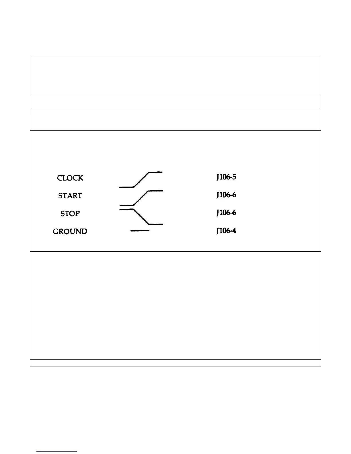
3. Connect signature analyzer CLOCK, START, STOP, and GROUND inputs as shown below.
Signature Analyzer Edge A2 Board Connection
Input Setting
4. Turn on the power supply and u the signature analyzer probe to take the following signatures:
Power: 5 V = 9FFP
Serial Link: A2U109-3 = 0l04
Microprocessor: A2Ul14-24 = 9FFP
A2U114-25 = UF39
Digital Control Interface:A2U118-1 = 9AFI
A2U118-9 = 40A5
A2U118-10 = l029
A2U118-15 = 00l0
A2U118-16 = 040A
Gated Array Logic: A2U119-2 = 0A55
A2U119-5= 0040
A2U119-15 = 0040
5. After completing the tests, be sure to return the J106 jumper to its original position.
 Loading...


