82 Principles of Operation
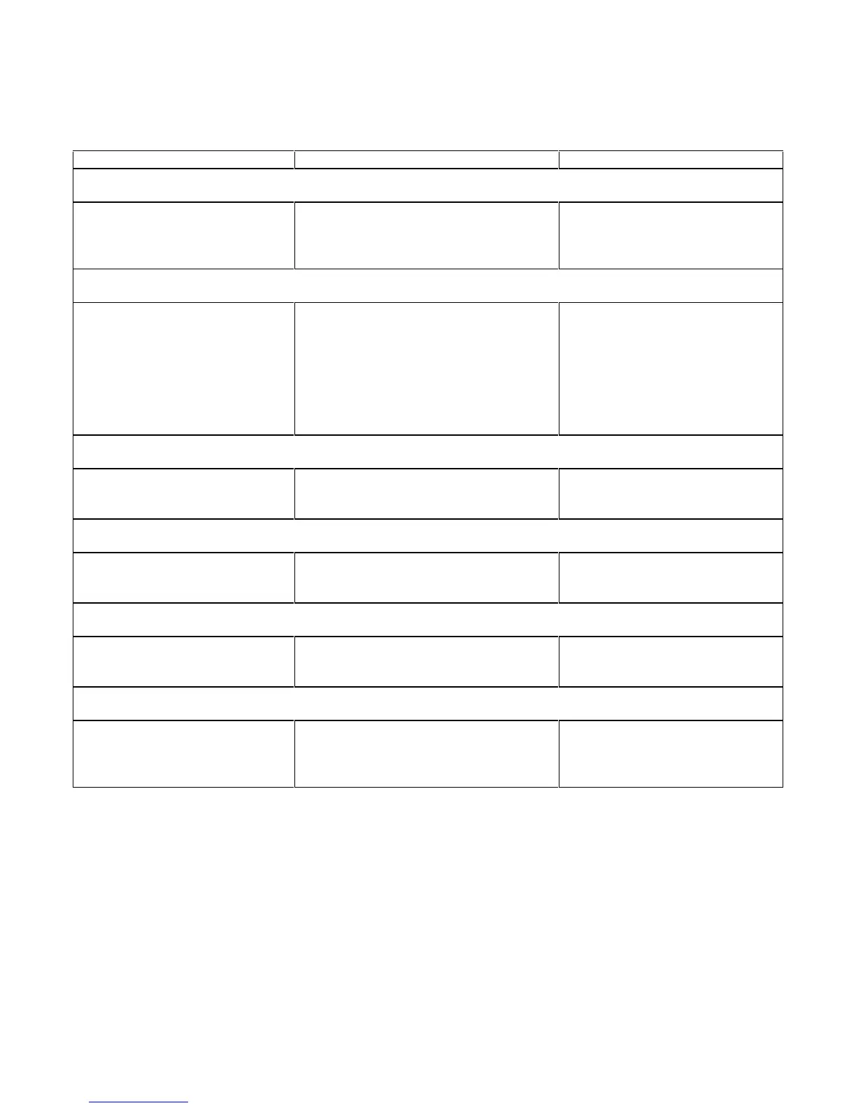
Table 4-1. Power Supply Interface Signals
Pin Signal Description
Output Power Connections
1
Busbar or terminal strip screw
terminals
+OUT
-OUT
Positive DC output voltage
Negative DC voltage (or return)
7-Pin I/O Analog Connector
Pin 1
Pin 2
Pin 3
Pin 4
Pin 5
Pin 6
Pin 7
IP
VP
+Imon
-Imon
ÏP
+S
-S
Current Programming
Voltage Programming
External Current Monitor
External Current Monitor
Programming Common
+Sensing Terminal
2
-Sensing Terminal
Rx/Tx Serial Link (Used with GPIB Models 664xA and 665xA only)
3
J1 and J2 Connectors wired in
parallel (daisy chain fashion)
3-lines; Rx, Tx, and common signals for
both Jl and J2 connectors.
Jl and J2 are telephone connectors.
AC Input Power Source
AC power connector, J451 Can be 100 V AC, 120 V AC, 220 V AC or
240 V AC
Input AC power
TB101 Digital Control (DIG CNTL) for 664xA and 665xA Models only
Pins 1 through 4 Pins 1 through 4 can supply one of three
sets of signals
See Table 4-2 for these I/O signals
and pin destinations.
GPIB Interface Connector (Used With Agilent Models 664xA and 665xA only)
GPIB IEEE multi-pin connector signals. See
Chapter 6, Figure 6-3, Sheet 2 (Zone 8A)
for these signals.
IEEE 488 type connector provides
the interface between an external
computer and the GPIB board.
1
For the 500 watt Agilent 655xA and 665xA models, the +OUT and -OUT signals connect to bus-bar type, screw
terminals . For the 200 watt Agilent 654xA and 664xA models, these connections are made at a terminal strip on the
power supply.
2
A switch on the A1 Main Board selects either "Remote" sensing or "Local" sensing of the output voltages (+OUT and
-OUT) leads to be monitored.
3
The Rx and Tx serial link permits up to 16 Agilent power supplies to be connected in a daisy chain fashion, each with its
own unique programmed device address. One GPIB address with other units being subaddressed.
 Loading...


