Chapter 4 227
Troubleshooting the Analyzer
Troubleshooting the A2 Display Assembly
Troubleshooting the A2 Display Assembly
Use this section when the A8 power supply is functioning but there
appears to be a defective A2 display assembly. Check the following
conditions before proceeding with the A2 display troubleshooting
procedures.
❏ Check that the B1 Fan is running and the green LED above the
LINE
switch is on when the analyzer is on. If they are not operating, refer
to the appropriate section of “Troubleshooting an Inoperative
Analyzer.”
❏ Check the five LEDs on the A8 power supply assembly. If they are
not on, refer to the appropriate section of “Troubleshooting an
Inoperative Analyzer.”
Note that the A8 power supply draws current whenever ac line
power is applied, even when the LINE switch is in the STANDBY
position. However, no voltages are distributed outside the A8 power
supply assembly when the LINE switch is in the STANDBYposition,
except for a TTL high on LPWRON.
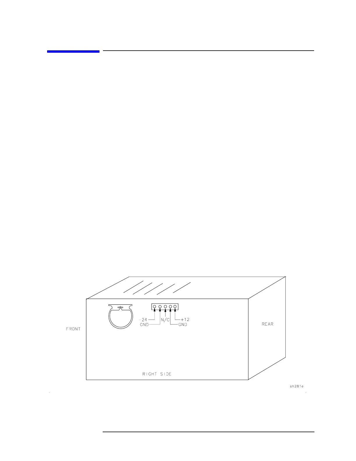
❏ Check the dc power supplied to the A2 display. There is a separate
12 V supply for the display assembly. This supply can be checked at
the output connector, A8J6, located on the right side of the A8 power
supply. Refer to Figure 4-3. If there is a failure, check the continuity
of the cable assembly W51 supplying the display, and the integrity of
the power supply using the procedures in this chapter.
Figure 4-3 Detail of Power Supply Connector, A8J6
 Loading...

