284 Chapter6
Troubleshooting the RF Section
6a. 8590L, 8591C, and 8591E
6a. 8590L, 8591C, and 8591E
This section describes the RF section troubleshooting process for the 8590L
and 8591E spectrum analyzers and 8591C cable TV analyzers.
Making RF Power-Level Measurements
The power level ranges listed for measurements A through G in
Table 6-1 apply after performing the following steps:
1. Connect the CAL OUT to the RF INPUT using the CAL cable.
Ensure that the CAL OUT amplitude is within specification. (Refer to
the calibrator amplitude performance test in the calibration guide.)
2. Perform the frequency and amplitude calibration routines.
3. Press PRESET, then wait for the analyzer to complete the preset routine.
4. Press the following instrument keys:
FREQUENCY, 300, MHz
SPAN
, 0, Hz
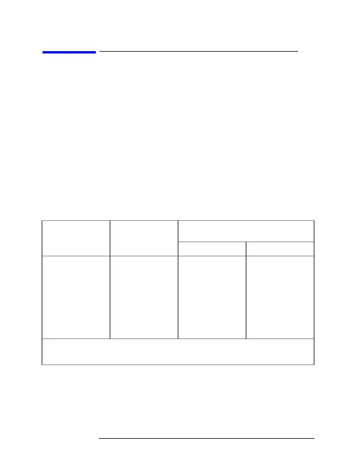
Table 6-1 Power Levels at Measurement Points
Measurement Point Measurement
Frequency
Power Level Range *
(dBm)
50 Ω 75 Ω
A 300 MHz −29 to −31 −35 to −37
B 2.1214 GHz −39 to −43 −46 to −49
C 2.1214 GHz −39 to −44 −46 to −50
D 321.4 MHz −42 to −46 −51 to −55
E 2.4214 GHz +6 to +12 Same as 50 Ω
F 2.4214 GHz −10 to −20 Same as 50 Ω
G 1.8 GHz −17 to −23 Same as 50 Ω
* A frequency-selective measuring device, such as another analyzer, is recommended for making these
measurements. Broadband measuring devices, such as power meters, give erroneous results due to the presence
of other, higher-amplitude signals.
 Loading...

