Chapter 6 285
Troubleshooting the RF Section
6a. 8590L, 8591C, and 8591E
Connector Pin-Out Information
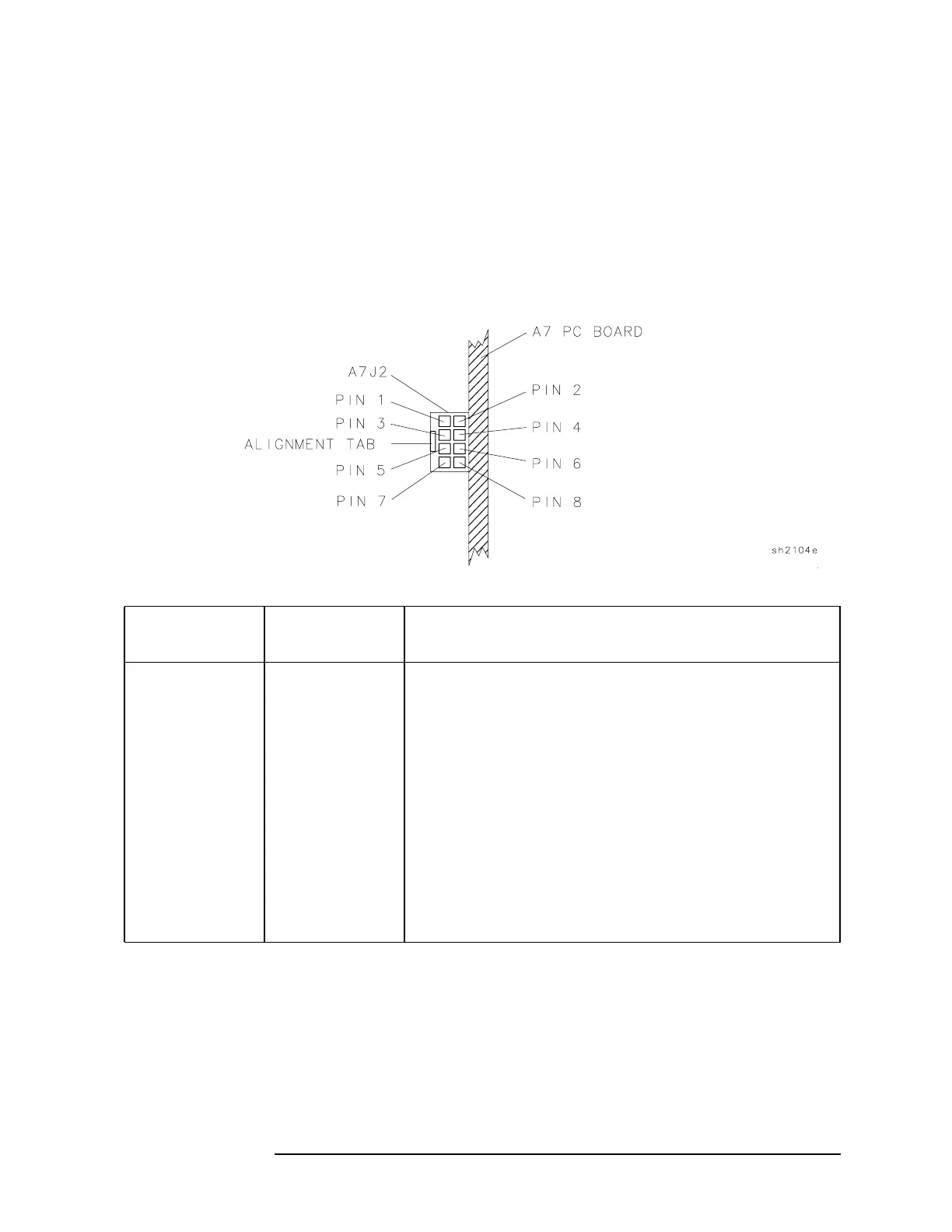
The RF section receives control voltages for the A3 attenuator from the A7
analog interface assembly. It also receives power-supply voltages for the A3
attenuator and A5 second converter assemblies from the A7 analog interface
assembly. The W13 wire harness connects the attenuator and second converter
to the A7J2 connector on the A7 assembly. Table 6-2 identifies the signals that
are supplied to the two RF assemblies and Figure 6-1 shows the pin number
location on A7J2.
Figure 6-1 A7J2 Pin-Out
Table 6-2 A7J2 Connector Pin Designation (Top-Side View)
A7J2
Pin Number
W13
Wire Color
Signal Description
1 Brown +8 VF power supply for A5 Second Converter
2 Black Analog ground for A5 Second Converter
3 Orange +15 VF power supply for A3 Attenuator
4 N/C
5 Green Control line for 20 dB step
on A3 Input Attenuator
6 Blue Control line for 10 dB step on A3 Input Attenuator
7 N/C
8 Grey Control line for 30 dB step on A3 Input Attenuator
 Loading...

