1-74
Making Measurements
Using Limit Lines to Test a Device
5. To terminate the flat line segment by establishing a single point limit, press:
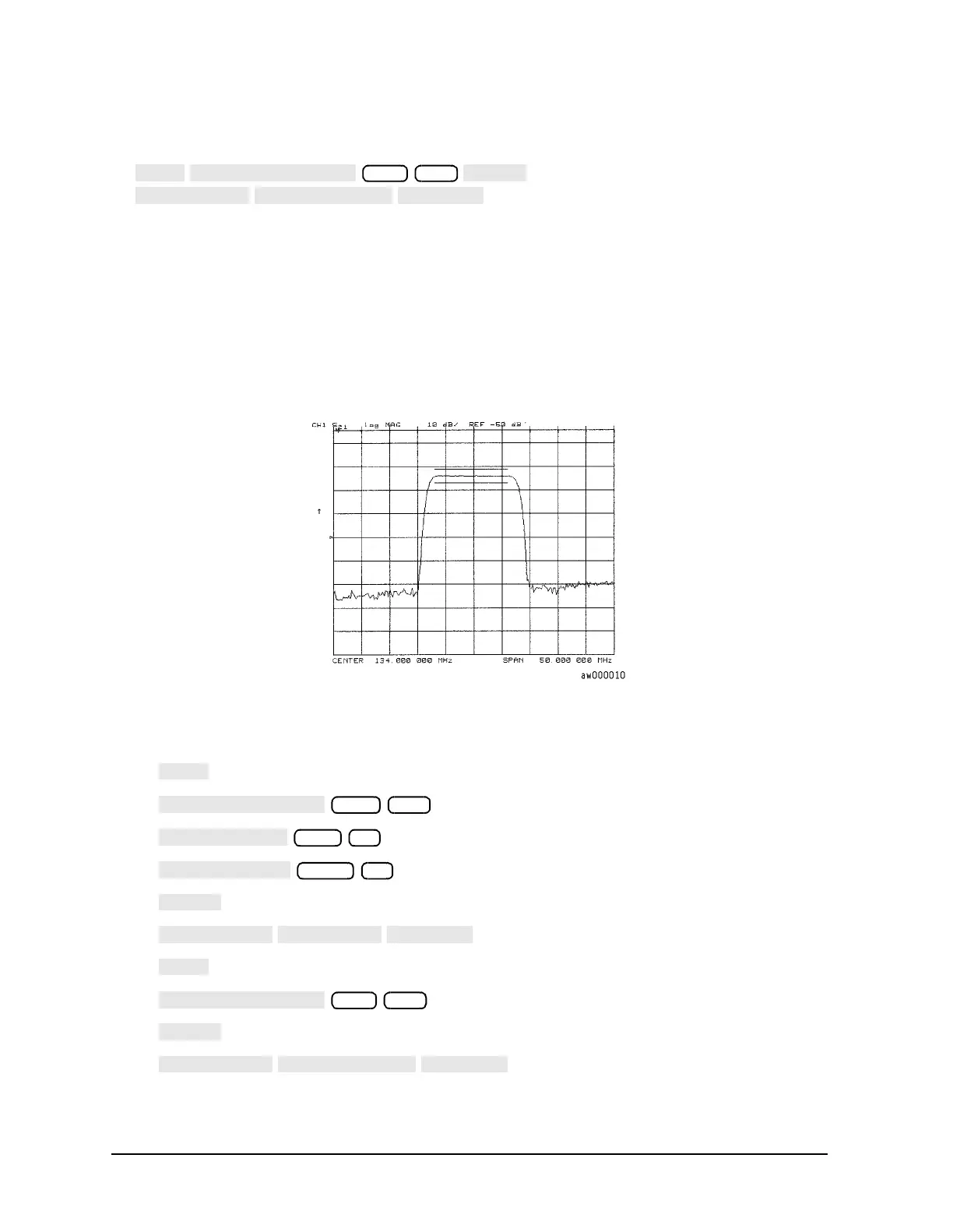
Figure 1-59 shows the flat limit lines that you have just created with the following
parameters:
• stimulus from 127 MHz to 140 MHz
• upper limit of −21 dB
• lower limit of −27 dB
Figure 1-59 Example Flat Limit Line
• To create a limit line that tests the low side of the filter, press:
140
100 M/µ
−65 x1
−200 x1
123 M/µ



 To Next Page