Chapter 3 Front-Panel Operation
Programming Overvoltage Protection
32
3 Clear the overvo ltage condition and exit this menu.
Now , when you pre ss key again, t he “DONE” message is displayed f or a
second and the
OVP
annunciator will not blink any more. The output will return
to meter mode.
• Adjust OVP trip level
1 Raise the OVP trip level.
Press key and turn the knob to raise the OVP trip level.
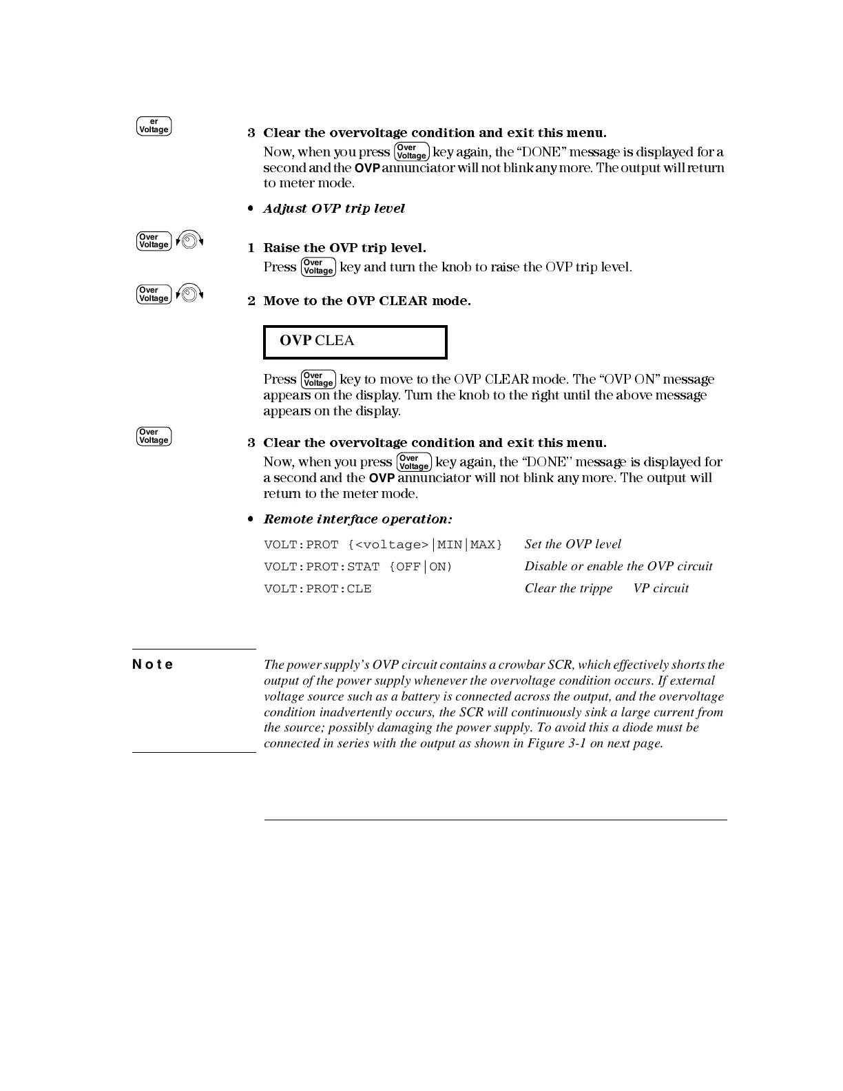
2 Move to the OVP CLEAR mode.
Press key to move to the OVP CLE AR m ode. The “OVP ON” message
appears on the display. Turn the knob to the right until the above message
appears on the display.
3 Clear the overvo ltage condition and exit this menu.
Now, when you press key again, the “DONE’’ message is displayed for
a second and the
OVP
annunciator will not blink any more. The output wil l
return to the meter mode.
• Remote interface operation:
VOLT:PROT {<voltage>|MIN|MAX} Set the OVP level
VOLT:PROT:STAT {OFF|ON) Disable or enable the OVP circuit
VOLT:PROT:CLE Clear the tripped OVP circuit
Note The power supply’s OVP circuit contains a crowbar SCR, which effectively shorts the
output of the power supply whenever the overvoltage condition occurs. If external
voltage source such as a battery is connected across the output, and the overvoltage
condition inadvertently occurs, the SCR will continuously sink a large current from
the source; possibly damaging the power supply. To avoid this a diode must be
connected in series with the output as shown in Figure 3-1 on next page.
OVP CLEAR
Over
Voltage
Over
Voltage
Over
Voltage
Over
Voltage
Over
Voltage
Over
Voltage
Over
Voltage
Over
Voltage

 Loading...


