ESG Family Signal Generators Front and Rear Panel
Rear Panel Overview
User’s Guide 3-13
1. AC Power Receptacle
The power cord receptacle accepts a three-pronged cable that is shipped with the
instrument. The line voltage is connected here.
2. GPIB Connector
The GPIB connector allows communications with compatible devices such as external
controllers. It is functionally equivalent to the AUXILIARY INTERFACE connector.
3. SYMBOL SYNC OUT Connector
The TTL/CMOS compatible SYMBOL SYNC OUT connector outputs a symbol
synchronization pulse, one data clock period wide, for use in digital modulation
applications. The pulse output is synchronized with the first symbol in the internal pattern
generator sequence. The damage levels are > +8 and <
−
4 V. This female BNC connector is
provided only on instruments with Option UND or UN8. If you configure your instrument
with Option 1EM, this output is changed from a BNC to an SMB connector. With
Option 201 you can select from several different output signals for this connector.
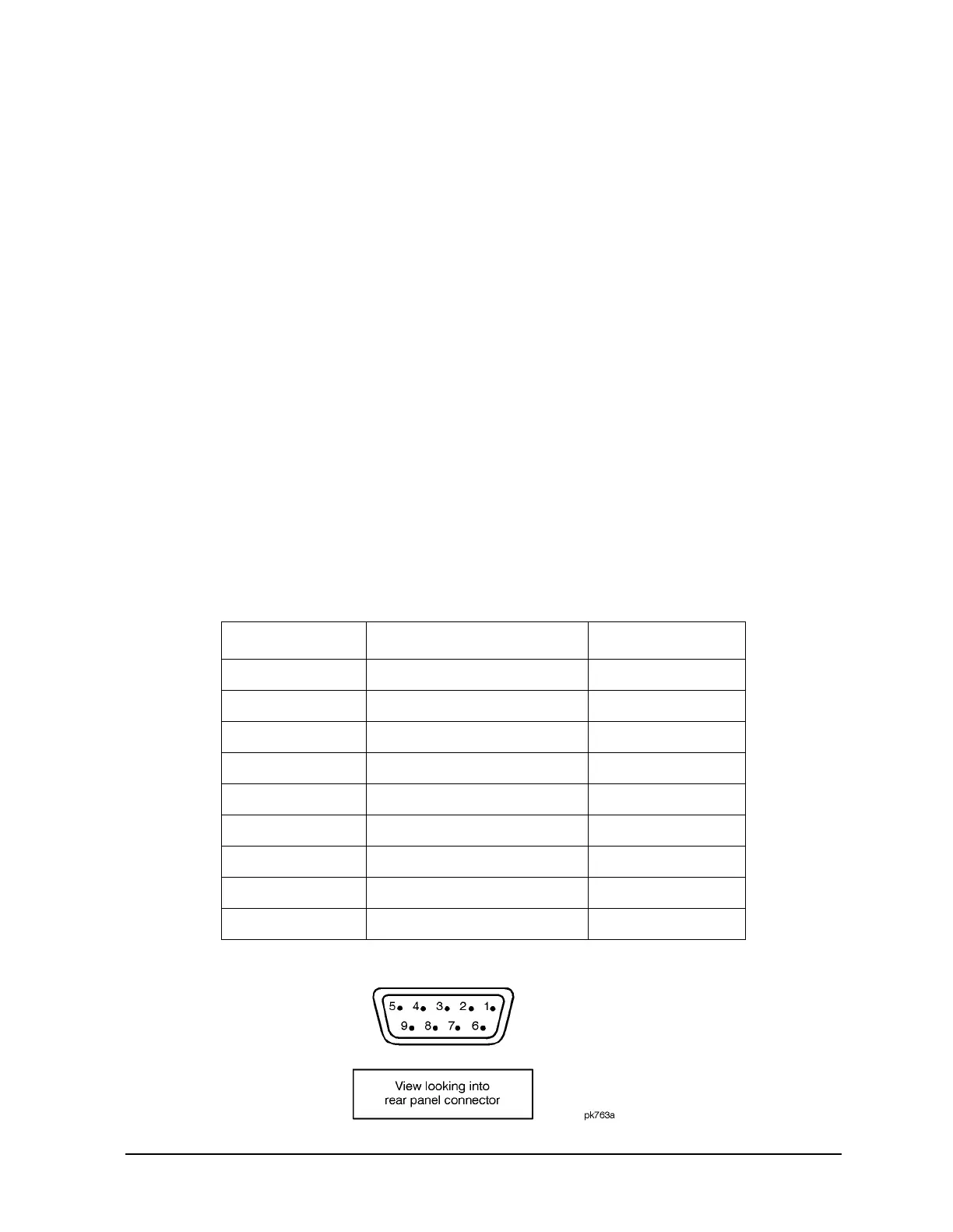
4. AUXILIARY INTERFACE Connector
This male DB-9 connector is an RS-232 serial port that can be used for controlling the
signal generator remotely. It is functionally equivalent to the GPIB connector. The
following table shows the description of the pinouts.
Pin Number Signal Description Signal Name
1 No Connection
2 Receive Data RECV
3 Transmit Data XMIT
4+5 V
5 Ground, 0 V
6 No Connection
7 Request to Send RTS
8 Clear to Send CTS
9 No Connection