4-26 Service Guide E8364-90038
Troubleshooting PNA Series Microwave Network Analyzers
Measurement System Troubleshooting E8362C, E8363C, E8364C
Verifying the A, B, R1, and R2 Traces (Standard S-Parameter Mode)
NOTE There is no way to view the frequency offset receiver response (Option 080). However, some
standard S-parameter receiver trace information is helpful in troubleshooting the frequency
offset section of the PNA. It is therefore recommended that you run this test even if you only
suspect the frequency offset section of malfunctioning.
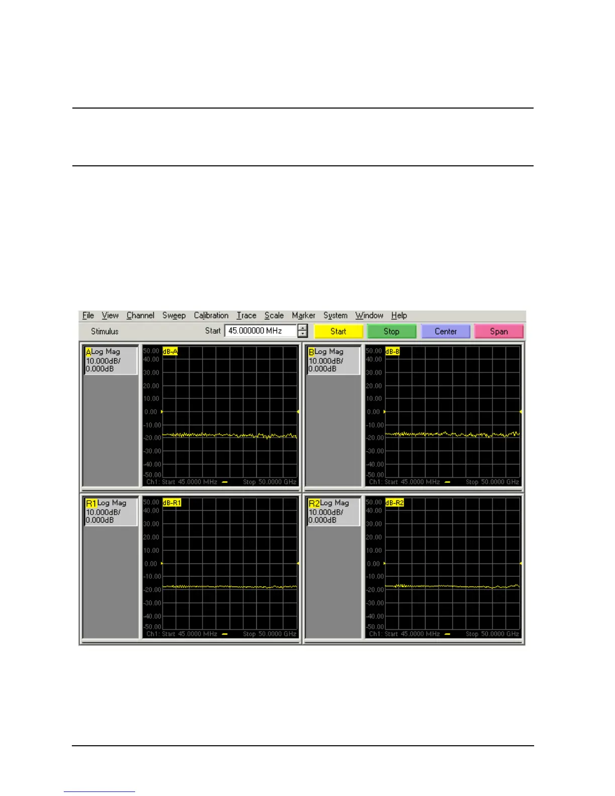
The first step is to verify that the A, B, R1, and R2 traces are present and that they are approximately level:
• Connect an Open or Short standard from a mechanical calibration kit to each test port (use adapters if
necessary).
•On the
System menu, point to Service, Utilities, and then click Receiver Display.
• Traces A, B, R1, and R2 are displayed in four separate data windows as shown in Figure 4-6. Identifying
discrepancies of the traces in these windows can help you to isolate the faulty assembly.
Figure 4-6 Typical Four Channel Display
 Loading...


