Service Guide E8364-90038 7-29
PNA Series Microwave Network Analyzers Repair and Replacement Procedures
E8362C, E8363C, E8364C Removing and Replacing the A15 CPU Board
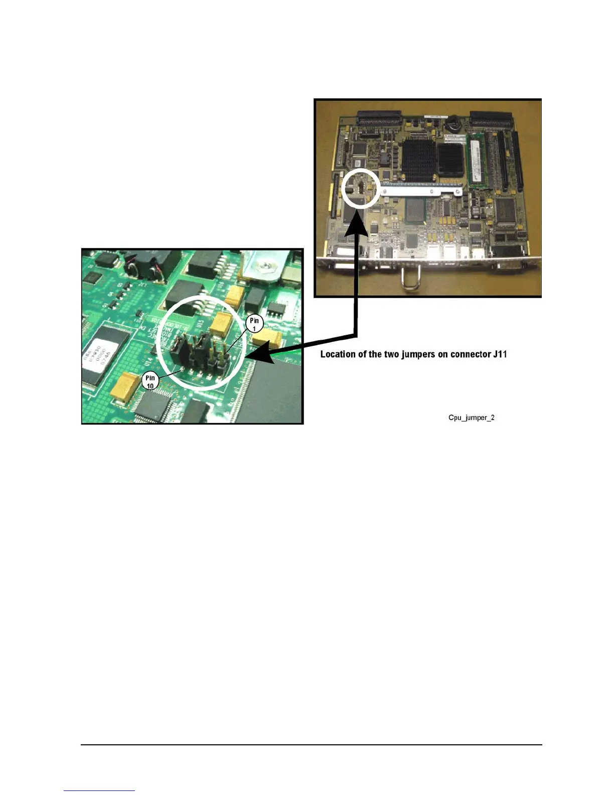
illustration for the J11 pin configuration. There should already be a jumper between pins 5 and 6.
1. Reverse the order of the removal procedure.
2. Perform the post-repair adjustments, verifications, and performance tests that pertain to this removal
procedure. Refer to Table 7-2 on page 7-82.
 Loading...


