3-48 Service Guide E8364-90038
Tests and Adjustments PNA Series Microwave Network Analyzers
Adjustments E8362C, E8363C, E836C
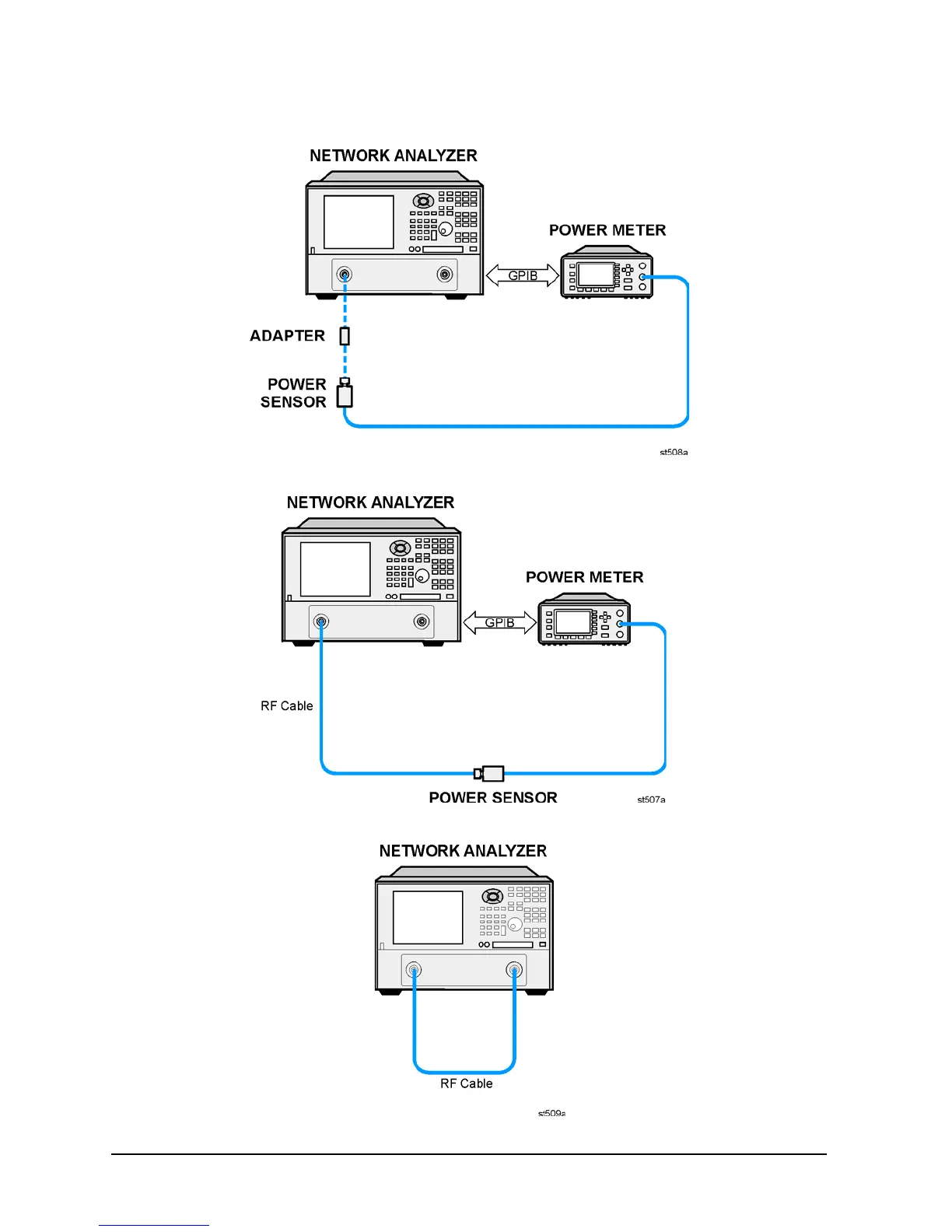
Figure 3-22 Setup 1 for the Receiver Calibration Adjustment
Figure 3-23 Setup 2 for the Receiver Calibration Adjustment
Figure 3-24 Setup 3 for the Receiver Calibration Adjustment