149
Repairing the Autosampler
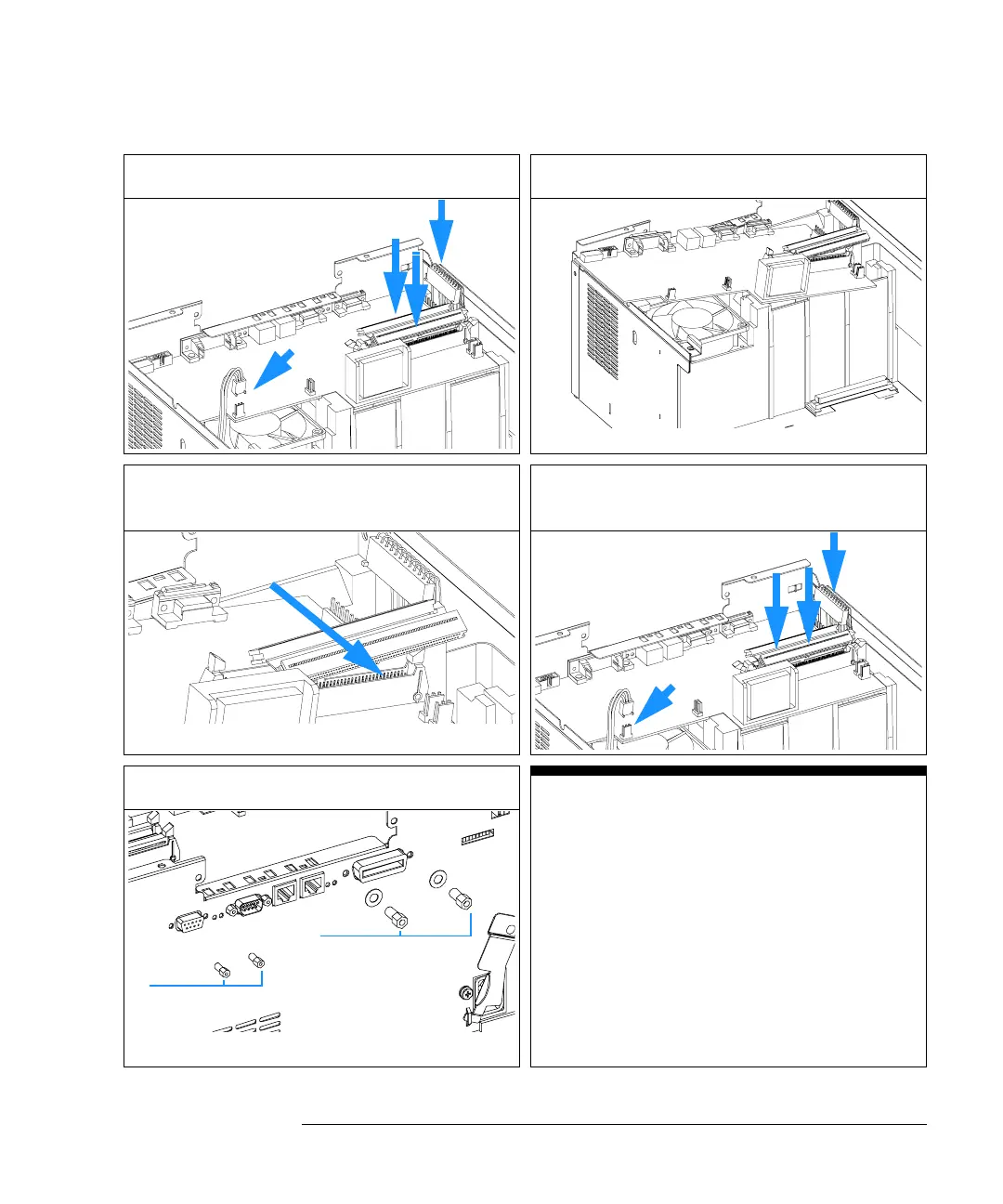
ASM Board
2 Disconnect all connectors on ASM board. 3 Slide ASM board out of the autosampler.
4 Install new board. Ensure ribbon cables are
positioned in the slot in the board.
5 Reconnect the connectors to the board.
6 Replace GPIB and RS232 connector screws.
On completion of this procedure:
On the new board check the switch setting
of address switch S1, see Table 53 on page
236, or Table 54 on page 237.
Note:
An incorrect switch setting (e.g., TEST/
BOOT) may cause the autosampler to turn
in a basic mode (yellow or red flashing
status light). In such a case turn off the
pump, re-set the address switches, and
turn on the pump again.
CellFrame
CellFrame
CellFrame
CellFrame
GPIB
screws
RS232
screws

 Loading...