Functions and Measurements 3
N9342C/43C/44C User’s Guide 45
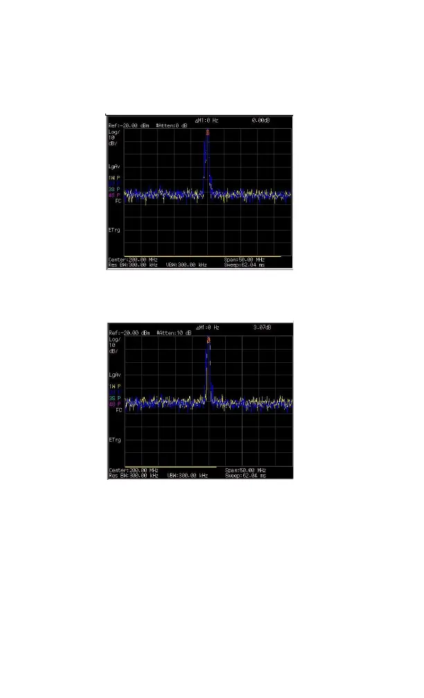
Figure 3-14 Identifying Analyzer Distortion (O dB atten)
8 Press [AMPTD] > {Attenuation} > 10 > {dB} to
increase the RF attenuation to 10 dB.
Figure 3-15 Identifying Analyzer Distortion (10 dB atten)
The marker readout comes from two sources:
• Increased input attenuation causes poorer
signal- to- noise ratio. This causes the marker
delta value to be positive.
• Reduced contribution of the analyzer circuits
to the harmonic measurement causes the
marker to be negative.
A large marker delta value readout indicates
significant measurement errors. Set the input
attenuator at a level to minimize the absolute value
of marker delta.
 Loading...


