Installation Note E8364-90024 15
Install the A46 Reference Switch
Refer to Figure 10 for this procedure. The new parts referenced in this procedure are listed in
Table 1 on page 4.
Before the A46 reference switch can be installed, the A25 test port 1 coupler and the A43
channel A receiver attenuator (Option 016 only) must be removed.
1. Option 016 only. Remove the A43 channel A receiver attenuator:
a.
Using a 5/16-inch wrench, disconnect the semirigid cables (item
①
) and (item
②
)
.
b. With a T-10 TORX driver, loosen the two mounting screws (item
③) and slide the
attenuator toward the rear of the analyzer to remove it from the mounting tabs.
c. Disconnect the ribbon cable from the attenuator and set the attenuator aside for
reinstallation later.
2. Remove the A25 test port 1 coupler:
a. Using a 5/16-inch wrench, disconnect the semirigid cables (item
④) and (item ⑤), if not
previously removed.
b. Using a 1-inch wrench remove the coupler nut (item
⑥).
c. Remove the test port coupler from the analyzer and set it aside for reinstallation later.
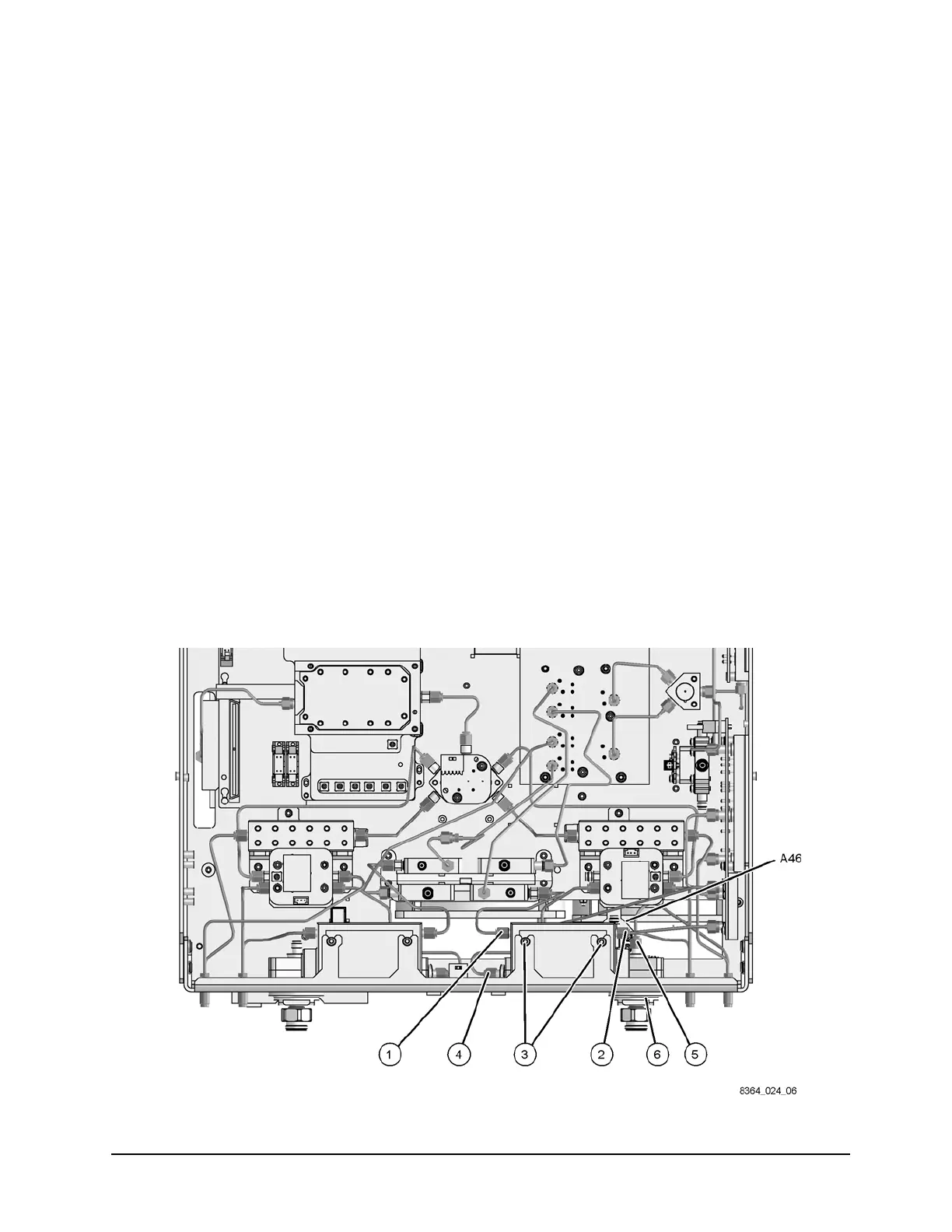
3. Place the A46 reference switch (provided) into position and, with a T-10 TORX driver,
install four M3.0 x 12 mounting screws (provided) to secure it to the test set deck.
Figure 10 A46 Reference Switch Installation
 Loading...


