DRAFT
10/9/14
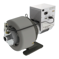
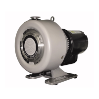
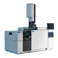
TriScroll 800 Inverter Vacuum Pump
4
Mechanical Connections
Pump Location
Locate the pump on a firm, level surface.
Clearance mounting holes provided in the frame can be
used to provide permanent attachment. Attach the
provided rubber mounts to the threaded holes at the
frame base to minimize vibration.
Do not to position the equipment so that it is difficult to
operate the disconnecting device.
Vacuum Pump Isolation Valve
Scroll pumps return to atmospheric pressure quickly
when shut off. Thus, an integrated fast acting, automatic,
normally closed isolation valve is standard equipment to
prevent pump debris from being transported back into the
vacuum chamber when the pump is turned off:
❑ The opening of this valve must occur 350 ms
after pump startup.
❑ Valve closing must occur 250 ms after pump
shut off.
The VPI Valve status is controlled by motor
operation. The VPI Valve:
❑ Opens when the pump is running and
❑ Closes when it is stopped due to switch off or
overload protection.
This TriScroll 800 Inverter Scroll pump includes the
necessary communication cable, needed to operate the
pump.
Pump Inlet
Use NW40, or larger, clean vacuum hardware with as
short a length as practical between the pump inlet and the
vacuum chamber.
Use a bellows to provide both vibration isolation and
strain relief between the pump and vacuum chamber.
Pump Exhaust
A female 3/8 National Pipe Thread exhaust fitting is
located underneath the scroll module. This fitting swivels
360°. Additionally, a NW25 adapter is provided with a
3/8 National Pipe Thread male thread.
Gas Ballast
The pump incorporates an automatic gas ballast to
prevent water and other condensates from accumulating
within the pump. The standard configuration is a sintered
filter installed in the 1/4" National Pipe Thread gas ballast
port (item 8 on Figure 1 on page 6). This allows enough
atmospheric air to enter the pump in order to purge
condensates while not affecting pump ultimate pressure
or pumping speed.
For applications where the ingress of atmospheric air is
undesirable, dry nitrogen at a flow rate of
5 lpm can be
bled into the gas ballast port. See item 8 on Figure 1 on
page 6. Blocking of the gas ballast port is not
recommended.
Bearing Purge
A 1/4" National Pipe Thread bearing purge port (item 5 on
Figure 1 on page 6) protects the main crankshaft bearings
in applications where large amounts of water are being
pumped. In the standard configuration, this port is sealed.
To enable the bearing purge, dry nitrogen at a flow rate of
5 lpm can be bled into the bearing purge port. This gas
supply should be maintained at 2 psig or less and must be
kept below 5 psig.
See “Purge Kit” on page 12.